A normal variable resistor cannot directly control the speed of a motor since motors draw large amounts of current which would burn out the potentiometer. Instead, the small amount of current that the potentiometer can pass can be amplified into order to run the motor. This amplification can be achieved using Darlington Pair of transistors.
The circuit above shows a linear potentiometer connected Between Vs and 0V Such That the voltage at its wiper terminal will of always be somewhere at or Between these two voltages. The small amount of current flowing out of the potentiometer's wiper is amplified by two transistors, connected together in a configuration known as a 'Darlington pair'. The current from the potentiometer is amplified by the first transistor, and then again by the second transistor, greatly Increasing the amount of current That cans be controlled by the potentiometer.
There are, however, a couple of disadvantages of this simple circuit. Firstly, about 0.7V is lost in EACH of the transistor, so the maximum voltage cans That ever be applied to the motor is Vs - 1.4V. Secondly, the transistors are not absolutely linear so the change in motor speed for a given rotation of the potentiometer will from some more subtle in the middle of its range. Because a motor is an inductive load, it will from Produce a 'back-emf' Could the which damage to the second transistor. The 1N4148 signal diode prevents this damage by shorting out the back-emf.
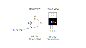
The power supply for this circuit should preferably be un-smoothed (i.e. directly from the power supply rectifier). This helps prevent the motor 'sticking' at low speeds. With the TIP31C transistor given, the maximum power supply voltage may be 60V and the maximum motor current consumption may be 3A.
Source: www.eleinmec.com

