Tuesday, November 29, 2011

AT89s51-52 and AVR USB Downloader

Microcontroller T89s51, AT89S52 and AVR is an idol among students. Well now because of technology trends and laptop PCs already left the LPT and COM so more and more difficult to download the firmware into the microcontroller, via LPT or COM. Solutions to be overcome with AT89S S-series, because the facility program downloads with the ISP (MISO, MOSI, SCK, RST), then use the ISP downloader which is also commonly used for this AVR microcontroller type. Time to play man with AT89s so much easier via USB without hassle and unplug the IC.
AT89s51-52 and AVR
USB Downloader Circuit

After you finish creating the PCB from the circuit above, then fill it to the ATmega8 with firmware usb51.hex do not forget to set low fuse = EF (SUT0 = 0, others = 1) and high fuse = C9 (SPIEN = 0, CKOPT = 0, BOOTSZ1 = 0, BOOTSZ0 = 0, others = 1). Of course, charging into the ATmega8, firmware downloader tool is needed.

For those who need a filling firmware and more complete information about the USB Downloader please visit http://guru.technosains.com/

Wednesday, November 16, 2011

Rangkaian Pendeteksi Angin

This circuit uses an incandescent lamp to detect airflow (mendeteksi angin). With the filament exposed to air, a constant current source is used to slightly heat the filament. As it is heated, the resistance increases. As air flows over the filament it cools down, thus lowering it's resistance. A comparator is used to detect this difference and light an LED. With a few changes, the circuit can be connected to a meter or ADC to provide an estimation on the amount of air flow. 
Rangkaian Pendeteksi Angin
LM339 Pinout
The glass will have to be removed from L1 without breaking the filament. Wrap the glass in masking tape and it in a vise. Slowly crank down until the glass breaks, then remove the bulb and carefully peel back the tape. If the filament has broken, you will need another lamp.

List Component
R1   : 100 Ohm 1/4W Resistor 
R2   : 470 Ohm 1/4W Resistor 
R3   : 10k 1/4W Resistor 
R4   : 100K 1/4W Resistor 
R5   : 1K 1/4W Resistor 
C1   : 47uF Electrolytic Capacitor 
U1   : 78L05 Voltage Regulator 
U2   : LM339 Op Amp 
L1   : #47 Incandescent lamp with glass removed (See "Notes") 
D1   : LED 

Stepper Motor Controller using IC 4027

The stepper controller circuit is very interesting, since most lines the step motor controllers are very expensive. The circuit is made ​​of standard components and can easily be adjusted by a computer. If you cheap surplus transistors and stepper motors, the price of the circuit can be less than $ 15.
Stepper Motor Controller Circuit using IC 4027
This stepper controller circuit shown here can used to control the unipolar stepper motor, the which has four coils. The stepper controller circuit can drive for a motor current of up to about 500 MAMP / Winding by Suitable heat sinks for the SL-100 In higher currents seem 2N3055 power transistors can be used as darlington pair along with the SL-100. All diodes are used to protect the transistor from back current transients.

List Componet
R1, R2 ,R3, R4: 1K 1/4W Resistor
D1, D2, D3, D4: 1N4002 Silicon Diode
Q1, Q2, Q3, Q4: TIP31 NPN Transistor (See Notes) TIP41, 2N3055
U1            : 4070 CMOS XOR
U2            : 4027 CMOS JK Flip-Flop
S1            : SPDT Switch
 
Notes: 
1. You should be able to substitute any standard (2N3055, etc.) power transistor for Q1-Q4.
2. Every time the STEP line is pulsed, the motor moves one step.
3. S1 changes the motors direction.
4027 CMOS JK Flip-Flop IC  Pinout
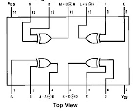
4070 CMOS XOR IC Pinout

Sunday, October 30, 2011

Ukuran Box Subwoofer 10"

This subwoofer box was created to match and aid the 1.618 Hi-Vi 3-way tower loudspeakers. The main focus of the HiVi 10" subwoofer was to reproduce ultra low frequencies that the 1.618 could not reproduce and aid in overall low end musical reproduction. Low, flat and not "boomy" was priority one. This subwoofer project uses the 10" subwoofer driver which can deliver plenty of bottom end.

The enclosure design and model frequency response are shown below.
Ukuran Box Subwoofer 10

Note:
  • 10" 4 ohm subwoofer
  • O-Audio 500 Watt plate amplifier
  • Freq Response: 25Hz up to chosen x-over point.
  • Overall Dimension: 21"x 12.75"x 20"

For more details on how to make it please read more http://diyaudioprojects.com/Speakers/HiVi-DIY-Subwoofer/

4,8W Class-A MOSFET Amplifier

This is very simple Class-A 2SK1058 MOSFET Amplifier circuit. It is easy to build it, Must use supply volte 24V at high current. It produces the most purest sound. I have no idea of distortion levels etc. but it has a very fine grain, and delicately textured quality.
4,8W  Class-A MOSFET Amplifier CircuitSkema Rangkaian 4,8W Class-A MOSFET Amplifier

2SK1058 Pin DiagramThis is one package 2SK1058 N-Channel MOSFET Pin Diagram

The four resistors are 15ohm and 10W each the which I wired two in series for 30 ohms and then the two sets of 30 ohms are wired in parallel to give a total resistance of 15 ohms. These get extremely hot and burn about 30W at idle.


For more detail please read more http://diyaudioprojects.com/Solid/ZCA/ZCA.htm

LM383 - Car Audio Amplifier Circuit

Circuit schematic shows the circuitry for a Class B amplifier with 8 Watt output, based on the LM383 chip. This amplifier circuit suited for automotive applications. High current capability (3.5A) en-ables the device to drive low impedance loads with low dis-tortion. The LM383 is Current Limited and thermally protected. High voltage protection is available (LM383A) the which enables the amplifier to withstand 40V transients on its supply. The LM383 comes in a 5-pin TO-220 package. By National Semiconductor Corporation
Amplifier berbasis LM383 Skema Rangkaian Car Audio Amplifier
berbasis LM383

Note:
That it's advised you use this with a LM383 chip Suitable heatsink.

LM383 chip pin
This is one package pinout of LM383 chip, If you need more pinouts please download LM383's pdf datasheet.

Friday, June 10, 2011

Rangkaian Power Amplifier Blazer 1000 Watt

This is a audio power amplifier Blazer circuit provides up to 1000Watt . This interesting routes many good bass and treble alive. Importantly should choose Power supply source, which has been fairly high voltage class 70Vdc GND -70V 10A is the current low level

Rangkaian Power Amplifier Blazer 1000 WattSkema Rangkaian Power Amplifier Blazer 1000 Watt

The transistors are 2SC3858 (NPN) and 2SA1494 (PNP), and feature high bandwidth, excellent safe operating area, high linearity and high gain. Driver transistors are 2SC5200 (NPN) and 2SA1943 (PNP). All devices are rated at 230V, with the power transistors having a 150W dissipation and the drivers are 50W.

This circuit describes an amplifier, power supply and tests procedures that are all inherently dangerous. Nothing described in this article should even be considered unless you are fully experienced, know exactly what you are doing, and are willing to take full 100% responsibility for what you do. There are aspects of the design that may require analysis, fault-finding and/or modification.

Tuesday, June 07, 2011

500 Watt Inverter 12VDC to 220VAC

The circuit of 500 Watt Inverter 12VDC to 220VAC is made using a transistor. central component of this inverter circuit is a configuration of 2 pieces of transistors Q1 and Q2 which form a circuit of Flip-Flop. The output of the flip-flop Q1 and Q2 then in severance for each pulse to complement each other using a compiled circuit by Q3 and Q4. Output which complement each other is then given to the driver transistors Q5 and Q6 form the transistor 2SC1061. Power Inverters of this circuit is composed using parallel transistors Q7, Q8 and Q7x, Q8x a form of 2N3055 power transistor 10 pieces. schematic a complete of Inverter 500 Watt circuit can be seen as follows.
Rangkaian 500 Watt Inverter 12VDC to 220VACSkema Rangkaian 500 Watt Inverter
12VDC to 220VAC

Step up part of this inverter circuit using a transformer 12VCT/500VA in secondary and primary 0 - 220V. While the frequency is determined by the flip-flop which is set to 50 Hz.

Note:
  • Q7, Q8 and Q7x, Q8x require heat sink.
  • Output power of this dc dc converter is around 500 watts.
  • An optional 40A fuse can be added in circuit to the 12V supply line.
  • T1 can be a 12-CT-12V /250V/40A mains transformer.

12VDC – 220VAC Inverter Using Cmos CD4047

This inverter circuit will convert 12V DC power from battery to 22oV AC as home power replacement. The inverter can be used for small electronic appliances such as lamp, radio, phone charger, disk player etc.
12VDC – 220VAC inverter circuitSkema Rangkaian 12VDC – 220VAC Inverter
Using Cmos CD4047

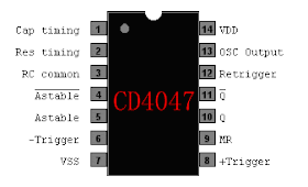
CD4047 Pinout

The inverter circuit has a central component, the CMOS 4047, and converts a 12V DC voltage to 220V AC voltage. 4047 is utilised as a astable multivibrator. At pin 10 and 11 we find a rectangular symmetrically signal which is amplified by tow Darlington transistors T1 and T2 and finally reaches the secondary coil of a transformer network (2 x 10V/100VA). Primary coil terminals voltage is 220 alternative voltage. To obtain a better performance use a toroidal core transformer with reduced losses. With P1 the output frequency can be regulated between certain limits (50…400Hz).


This Circuit From: http://apowersupply.com

Thursday, May 19, 2011

Light/Dark Switch With Relay

The circuit as shown act as a light detector. Under normal conditions the resistance of the LDR is high, keeping pin 2 low. When light falls onto the LDR the resistance drops to a couple hundred ohms and triggers pin 2 high which biases the base of Q1 via pin 6 and R4 and in turn activates the relay.

Light/Dark switch with relayLight/Dark switch Circuit with relay

As you may have notice, the 741 is connected as a voltage comparator. Two voltage dividers are easy to be found: The first one is the10K resistor and the LDR . The second one is composed by the two 470 Ohms resistors and the potentiometer. Both the outputs of the dividers are connected as inputs to the voltage comparator.

The second voltage divider will settle the reference voltage. The first voltage comparator that contains the LDR, will change it's voltage according to the light level. When the voltage across the negative input of the comparator is less than the voltage to the positive input of the comparator, the output is held low. When the voltage on the negative input rises, there will be a time that it becomes greater than or equal to the positive (pre-selected) voltage, and then the output becomes high and the relay through the 2N2222 is actuated.

Refrigerator Door Alarm Circuit Using LDR

The alarm circuit enclosed into a small box is placed in the refrigerator near the lamp. With the door closed the interior of the refrigerator is in the dark, the LDR R2 presents a high resistance thus clamping IC1 by holding pin 12 high. When a beam of light enters from the opening, or the refrigerator lamp illuminates, the LDR lowers its resistance, pin 12 goes low, IC1 starts counting and, after a preset delay (20 seconds in this case) the piezo sounder beeps for 20 sec. then stops for the same lapse of time and the cycle repeats until the refrigerator door closes. D2 connected to pin 6 of IC1 allows the piezo sounder beeping 3 times per second.
Refrigerator Door Alarm Circuit Skema Rangkaian Refrigerator Door Alarm Using LDR

Note:
  • Delay time can be varied changing C1 and/or R3 values.
  • Quiescent current drawing is negligible, so SW1 can be omitted.
  • Place the circuit near the lamp and take it away when defrosting, to avoid circuit damage due to excessive moisture.
  • Do not put this device in the freezer.

List Component:
R1    : 10K
r2 : LDR any type
R3,R4 : 100K
C1 : 10nF
C2 : 100µF/25V
D1,D2 : 1N4148
IC1 : 4060 14 stage ripple counter and oscillator IC
Q1 : BC337
BZ1 : Piezo sounder (incorporating 3KHz oscillator)
SW1 : SPST slide Switch
B1 : 3V Battery

This alarm circuit from : http://www.redcircuits.com/

Sunday, May 01, 2011

Rangkaian 11-90 hz Subwoofer Filter Using TL072 Op-Amp

The subwoofer filter circuit allows the addition of subwoofers to an existing full-range system, offering adjustable low-pass filtering with optional R6 and R8 boost and mono-summing.
Rangkaian 11-90 hz  Subwoofer Filter Skema Rangkaian 11-90 hz Subwoofer Filter
Using TL072 Op-Amp

TL072 Op-Amp

The Subwoofer filter circuit to remove for separate pre amplifier to drive the low frequency sound a lot. In tone, call tone, normal Can not be done … is a fine deep low bass sounds like a bass drum, or at a movie complex in a low voice if we can be heard with But to add cabinets and amps. The subwoofer circuit is pass low frequency with in 11-90 Hz. Switching power supply 12V cut out if they need to use +-15V. I had change the Capacitor to cut out vocals per the red circle mark.

6 Band Graphic Equaliser Circuit Using 741 Op-Amp

This circuit is 6 Band Graphic Equaliser ,you can adjust sound in low ,mid and high which circuit used IC 741 Op-Amp. With this circuit you can control and blend frequencies and tones as desired.

Essentially, the circuit consists of an IC 741 whose gain at various freguencies is determined by corresponding potentiometer setting.

6 Band Graphic Equaliser Circuit Skema Rangkaian 6 Band Graphic Equaliser Using 741 Op-Amp

The audiblefrequency spectrum is covered in six steps: 50Hz, 160Hz, 500Hz, 1.6kHz, 5kHz, 16kHz. All potentiometers are of 100kΩ linear type. The circuit provides adequate boost / cut for normal use.

power supply for the circuit can be derived from the amplifier / preamplifier itself. The wide rangeof supply voltage (6V-20V) makes the circuit very versatile. Power consumption is negligible.

list Component
R1,R2,R3,R4,R5,R6 : 27kΩ     C1: 100n      C6: 300pF
R7: 470kΩ C2: 33n C7: 100uF/16V
R8: 330kΩ C3: 10n C8: 4.7uF/16V
R9: 100kΩ C4: 3.3n C9: 47uF/16V
R10: 4.7kΩ C5: 1n IC1: 741 Op amp
R11: 4.7kΩ
VR1,VR2,VR3,VR4,VR5,VR6: 100kΩ Linear Potentiometers

Rangkaian 400W MOSFET Amplifier

These amplifiers circuit can be used for virtually any application that requires high performance, low use Noise, distortion and excellent sound quality. Examples would be subwoofer amplifier should FOH stage Amplifiers, surround a canal a very powerful sound amplifier, etc. The 400W MOSFET-amplifier has four key stages of amplification. We are looking to start any Phase appropriate detail.
Rangkaian 400W MOSFET  AmplifierSkema Rangkaian 400W MOSFET Amplifier

Note:
  • Use + /-70V 10A DC dual supply for powering the circuit.
  • For L1 make 12turns of enameled copper wire on a 1cm him: plastic formers.
  • use 8 x IRFP448 MOSFETs in the final stages
  • Heat sink is Necessary for the MOSFETs. A 8x4x4 inch finned aluminum heat sink will do. There is no such thing as a heat sink That is too large.

As the name suggests All Q ,C and ZD the Bias and buffer phases. Its main goal is to provide a stable MOSFET Gates and offset voltage and the voltage buffer amplifier stage of the High Resource capacity. What would have without the phase response and the effect Slew rate is indeed very bad. The flip side of the coin is not the extra step Introduction of an additional dominant pole in the amplifier feedback loop.

Also to what the name suggests this stage converts the voltage developed in the VAS and provides all the amps required to drive at 8 or 4 ohms. 2-ohm loads are possible for several minutes at a time. In fact, I have tested more than 1600 1kW amplifier Watts RMS at 2 ohms. But that would not be recommended as a long-term exposure at all. If it is higher than the figures of the STI-amp. Power to the AV amplifier 800 The components of the power for this amplifier are as follows, and are favored A channel or a power module alone. 1 toroidal transformer with a rating of 1kVA. Primary windings are made to fit

Audio Peak Level Indicator By Op-Amp

simple circuit PEAK indicator of foliage of the musical signal. This circuit was designed to provide a valuable test equipment tool for sound reinforcement systems like sound amplifiers and the like. The circuit is formed by an input buffer and ac to dc voltage converter (IC1A) feeding a window comparator (IC2A, IC2B, IC2C) which illuminates one of three LEDs at a time.

Audio Peak Level Indicator By Op-AmpSkema Rangkaian Audio Peak Level Indicator By Op-Amp

No setup is required: if correct values are used for resistors R3 to R7, LED D1 will illuminate at 0dB input (0.775V RMS), LED D2 at +5dB input (1.378V RMS) and LED D3 at +10dB (2.451V RMS).

The circuit was optimized for low current consumption as it was intended for battery operation. To achieve this, the best arrangement has proven to be the one using two different op-amp types for IC1 and IC2. In fact the LM393 IC was not operating satisfactorily as dot-mode LED driver, whereas the LM324 was unable to charge C2 in the linear way, as expected. Therefore, the final circuit is some op-amp wasting, but the small added cost will be quickly compensated by battery savings.

List Component:
R1    : 300K         D1,D2,D3 : LEDs
R2 : 1M2 IC1 : LM393
R3 : 510K IC2 : LM324
R4 : 220K IC3 : 78L05
R5 : 91K SW1 : SPST Toggle or Slider Switch
R6 : 160K B1: 9V PP3 Battery
R7 : 56K
R8,R9 : 100R
R10 : 220R
C1 : 100nF
C2 : 1µF/63V
C3 : 10µF/25V

Wednesday, April 06, 2011

DC Motor Controller Circuit Using 741 Op-Amp

This DC motor controller circuit using a 741 operational amplifier operating as a voltage follower where its non inverting input is connected to the speed and rotation direction of a potentiometer VR1. When VR1 is at mid position, the op-amp output is near zero and both Q1 and Q2 is OFF.

When VR1 is turned towards the positive supply side, the output will go positive voltage and Q1 will supply the current to the motor and Q2 will be OFF. When VR1 is turned to the negative supply side, the op-amp output switches to the negative voltage and Q1 will turn OFF and Q2 ON which reverses the rotation of the motor's direction.

Simple DC Motor Controller CircuitSkema Rangkaian DC Motor Controller Using 741 Op-Amp

741 Op-Amp Pinout

As the potentiometer VR1 is moved toward either end, the speed increases in whichever direction it is turning. The TIP3055 Q1 NPN power transistor has a collector current specs of 15A and VCE0 of 60V DC. The MJE34 Q2 PNP power transistor has a collector current specs of 10A and VCE0 of 40V DC.

Rangkaian 3V FM Transmitter

This 3V FM transmitter is about the simplest and most basic transmitter to build and have a useful transmitting range. It is surprisingly powerful despite its small component count and 3V operating voltage. It will easily penetrate over three floors of an apartment building and go over 300 meters in the open air.

The circuit is basically a radio frequency (RF) oscillator that operates around 100 MHz. Audio picked up andamplified by the electret microphone is fed into the audio amplifier stage built around the first transistor. Output from the collector is fed into the base of the second transistor where it modulates the resonant frequency of the tank circuit (the 5 turn coil and the trimcap) by varying the junction capacitance of the transistor. Junction capacitance is a function of the potential difference applied to the base of the transistor. The tank circuit is connected in a Colpitts
Rangkaian 3V FM TransmitterSkema Rangkaian 3V FM transmitter

Place the transmitter about 10 feet from a FM radio. Set the radio to somewhere about 89 - 90 MHz. Walk back tothe FM transmitter and turn it on. Spread the winding of the coil apart by approximately 1mm from each other. No coilwinding should be touching another winding. Use a small screw driver to tune the trim cap. Remove the screwdriverfrom the trim screw after every adjustment so the LC circuit is not affected by stray capicitance. Or use a plasticscrewdriver. If you have difficulty finding the transmitting frequency then have a second person tune up and downthe FM dial after every adjustment. One full turn of the trim cap will cover its full range of capacitance from 6pF to 45pF. The normal FM band tunes in over about one tenth of the full range of the tuning cap.

So it is best to adjust it in steps of 5 to 10 degrees at each turn. So tuning takes a little patience but is not difficult. The reason that there must be at least 10 ft. separation between the radio and the FM transmitter is that the FM transmitter emits harmonics; it does not only emit on one frequency but on several different frequencies close to each other. You should have little difficulty in finding the Tx frequency when you follow this procedure.

25V Capacitor Bank for OCL Amplifier

Rangkaian 25V Capacitor Bank

The circuit diagram below shows how the +25V DC and -25V DC are obtained. In order to provide power supply for stereo amplifiers, a power transformer rating of 80VA with 240V/36V centre tapped secondary winding is used. The secondary output of the transformer is rectified by using four 1N5401 diodes together with 4 electrolytic capacitors to smoothen the ripple voltage. A fuse and a varistor are connected at the primary input to protect the circuit against power surge. Here you can see the circuit’sdiagram diagram

25V Capacitor Bank for OCL AmplifierSkeme Rangkaian 25V Capacitor Bank for OCL Amplifier

Basic Capacitor Bank for OCL Amplifier
Although shown with 4,700uF filter capacitors, larger ones may be used. Anything beyond 10,000uF is too expensive, and will not improve performance to any worthwhile degree. Probably the best is to use two 4,700uF caps per side (four in all). This will actually work better than a single 10,000uF device, and will be cheaper as well.

It is essential that fuses are used for the power supply. While they will not stop the amp from failing (no fuse ever does), they will prevent catastrophic damage that would result from not protecting the circuit from over-current conditions.

Wednesday, March 23, 2011

35W Audio Amplifier Circuit by STK082

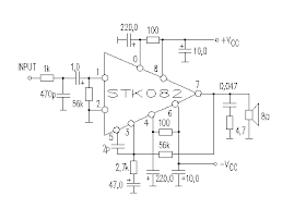
Here is a 35W audio amplifier circuit built based on single Amplifier chip STK082. This is a very simple amplifier, very easy to build and produce sound output with a fairly large power of 35 watts into 8 Ohm loads.
35W Amplifier Circuit by STK082  Skema rangkaian STK082 - 35W audio Amplifier

STK082  icThis amplifier circuit is suitable for home power audio devices. The STK082 amplifier specifications might lead you to believe that it can use supply voltages of up to ±43V. but I don't recommend anything greater than ±25V if 8 ohm loads are expected, although ±30V will be fine if you can provide good heatsinking.

Rangkaian Audio Surround Decoder

This circuit has been created to design a decoder circuit that will operate in a module that would produce an audio surround sound.

Rangkaian Audio Surround Decoder Skema Rangkaian Audio Surround sound Decoder


The operation of the above circuits starts as the stereo sound signal transports surround sound information on the master volume part of the circuit. This will drive the Left channel Lch attached to Model TL072 IC1A and IC1b in which Right channel Rch is attached. The outputs on these operational amplifiers would serve as the input buffer to the following stages of the circuit. IC2C is responsible for summing up the signals from the left and right channels that will power the central loudspeaker output while IC2D is responsible for increasing the phase difference between left and right channels which is encoded in the two channels and will be fed to the rear loudspeakers. It is necessary to ensure that the negative terminals between the rear speaker is not earthed because they will simply function in parallel with the main speakers.

The output of IC2D will power regulated delay unit of audio to the rear loudspeakers. This would lead to the creation of proper sense of spacing in accordance to the size of the room. This will incorporate op-amp sound delay signal IC5 MN3004 which has 512 stages. Since IC4 MN3101 is a clocking signal, it provides timing to IC5 as it functions as an oscillator in the circuit. Variable capacitor C17 regulates the delay time in the circuit. The presence of filters in the circuit is for the purpose of preventing noise that will be produced during the process. These filters can be regulated to cut the frequencies above 8 KHz and under 100 Hz, to be able to drive the rear speaker. The rear loudspeaker is small in size because its input is encoded with a bandwidth of 100 Hz up to 8 KHz. The filters are built around the IC6A/B which is also an output buffer. A potentiometer is placed in every output to aid in the adjustment and regulation of loudspeakers and amplifiers. The supplied power in the circuit is 15 V and every output can drive a single power amplifier.

List Compoment
R1-2-7-8-12-13-18-19-20 : 47Kohm
R3-4-5-6-21-22-34-35 : 10Kohm
R9-10-11-14-15-16-17 : 15Kohm
R23-24-25-33-36 : 100ohm
R26-27-28-31-32 : 100Kohm
R29-30 : 5.6Kohm
C1-8 : 47uF/25V
C2-7-9-14-23 : 47nF
C3-6 : 1uF/100V
C4-5-10 : 33pF
C11-12-15 : 10uF/25V
C13 : 82nF
C16 : 18pF
C17 : 100pF mini adjustable capacitor
C18 : 2.2nF
C19 : 4.7uF/25V
C20 : 100nF
C21 : 10nF
C22 : 180pF
C24 : 150nF
RV1-RV2 : 2 X 10Kohm Log. pot.
RV3-4 : 10K Log pot.
D1 : 1N4148
IC1-6 : TL072
IC2-3 : TL074
IC4 : MN3101
IC5 : MN3004

This Audio Surround Decoder circuit from www.circuit-projects.com

Rangkaian Charger aki 6 Volt

Here is the circuit diagram of a low cost charger for 6 volt batteries. This circuit requires a regulated 10V-DC front end capable of supplying 2 Amps. Begins the charge period at 240mA and at full charge switches automatically to a float condition of 12mA. The capacitors should be the electrolytic 25V or greater.

Rangkaian Charger aki 6 VoltSkema Rangkaian Charger aki 6 Volt
Switching transistor T1 is an TIP31C NPN transistor, Si-Power Output/SW, with a TO-220 case and can be changed by using a appropriate substitute such as the NTE291, ECG291, etc. Timer/Oscillator U1 is a 8-pin NE555V and can be changed with a NTE955M or ECG955M. Resistors R4, R5, R6, and R7 are 1% metal film types.

100Watt Inverter Circuit by IRF44 Mosfet

This inverter circuit will provide a very stable 230V Output Voltage. Frequency of operation is determined by a VR1 and is normally set to 60 Hz. Various “off the shelf” transformers can be used. Or Custom wind your own for best results. Additional MosFets can be paralleled for higher power. It is recommended to Have a “Fuse” in the Power Line and to always have a “Load connected”, while power is being applied. The Fuse should be10 Amps per 100 watts of output. The Power leads must be heavy enough wire to handle this High Current Draw

100Watt Inverter Circuit by IRF44 MosfetSkema Rangkaian 100Watt Inverter by IRF44 Mosfet

IRF44 PINNING

Absolute Maximum Ratings of IRF44 Mosfet
  • Continuous Drain Current (25°C, 10V) = 49 A
  • Continuous Drain Current ( 100°C, 10V) = 35 A
  • Pulsed Drain Current = 160 A
  • Power Dissipation = 94 W
  • Gate-to-Source Voltage = ± 20 V
  • Avalanche Current = 25 A
  • Operating Junction = -55 to + 175

Monday, March 07, 2011

12VDC to 220VAC Inverter Circuit Using IC 555

This is a simple 12VDC to 220AC inverter circuit that can be used produces an AC output at line frequency and 220AC or different voltage by selecting transformer T1. The 555 IC is configured as a low-frequency oscillator, tunable over the frequency range of 50 to 60 Hz by Frequency potentiometer R4.
12VDC to 220VAC Inverter Circuit 12VDC to 220VAC Inverter Circuit

The 555 feeds its output (amplified by Q1 and Q2) to the input of transformer T1, a reverse-connected filament transformer with the necessary step-up turns ratio. Capacitor C4 and coil L1 filter the input to T1, assuring that it is effectively a sine wave. Adjust the value of T1 to your voltage. The output ( in watts) is up to you by selecting different components.

Input voltage is anywhere from +5V to +15Volt DC, adjust the 2700uF cap's working voltage accordingly. Replacement types for Q1 are: TIP41B, TIP41C, NTE196, ECG196, etc. Replacement types for Q2 are: TIP42B, TIP42C, NTE197, ECG197, etc.

Friday, March 04, 2011

Smoke Detector circuit Using LDR

This is a simple Smoke Detector circuit based on a LDR and lamp pair for sensing the fire. It uses a very simple approach to detecting smoke in the air. The alarm works by sensing the smoke produced during fire. The circuit produces an audible alarm when the fire breaks out with smoke.
Smoke Detector circuitSmoke Detector circuit using LDR

When there is no smoke the light from the bulb will be directly falling on the LDR.The LDR resistance will be low and so the voltage across it (below .6V).The transistor will be OFF and nothing happens. When there is sufficient smoke to mask the light from falling on LDR, the LDR resistance increases and so do the voltage across it.Now the transistor will switch to ON.This gives power to the IC1 and it outputs 5V.This powers the tone generator IC2 to play a music.This music will be amplified by IC3 to drive the speaker.

The diode D1 and D2 in combination drops 1.4 V to give the rated voltage (3.5V ) to UM66 .UM 66 cannot withstand more than 4V.

Car Parking Sensor circuit Using Infra-Red LED

This circuit can be used for an assist in parking the car near the garage wall backing up Pls. LED D7 illuminates Pls bumper-wall distance is about 20 cm., D7 + D6 illuminate at about 10 cm. and D7 + D6 + D5 at about 6 cm. In this manner you are alerted Pls approaching too close to the wall.
Car Parking Sensor circuit Using InfraredCar Parking Sensor circuit

All distances mentioned before can vary, depending on infra-red transmitting and receiving LEDs used and are mostly affected by the color of the reflecting surface. Black surfaces lower greatly the device sensitivity. Obviously, you can use this circuit in other applications like liquids level detection, proximity devices etc.

Note:
  • The infra-red Photo Diode D2, should be of the type incorporating an optical sunlight filter: these components appear in black plastic cases. Some of them resemble TO92 transistors: in this case, please note that the sensitive surface is the curved, not the flat one.
  • Avoid sun or artificial light hitting directly D1 & D2.
  • If your car has black bumpers, you can line-up the infra-red diodes with the (mostly white) license or number plate.
  • It is wiser to place all the circuitry near the infra-red LEDs in a small box. The 3 signaling LEDs can be placed far from the main box at an height making them well visible by the car driver.
  • The best setup is obtained bringing D2 nearer to D1 (without a reflecting object) until D5 illuminates; then moving it a bit until D5 is clearly off. Usually D1-D2 optimum distance lies in the range 1.5-3 cm.
List Component of Car Parking Sensor circuit:
R1             : 10K
R2,R5,R6,R9 : 1K
R3 : 33R
R4,R11 : 1M
R7 : 4K7
R8 : 1K5
R10,R12-R14 : 1K
C1,C4 : 1µF/63V
C2 : 47pF
C3,C5 : 100µF
D1 : Infra-red LED
D2 : Infra-red Photo Diode (see Notes)
D3,D4 : 1N4148
D5-7 : LEDs (Any color and size)
IC1 : NE555
IC2 : LM324
IC3 : LM7812

Monday, February 21, 2011

UM3561 - Simple Sound Effects Generator Circuit

This is a very simple. The IC UM3561 produces four differen sound effects, the output at Pin 3 being amplified by the transistor 2N2222. A 64 ohm loudspeaker can be substituted in place of the 56 ohm resistor and 8 ohm loudspeaker.
Sound Effects Generator circuitSkema Rangkaian Sound Effects Generator

The 2 pole 4 way switch controls the sound effects. Position 1 (as drawn) being a Police siren, position 2 is a fire engine sound, 3 is an ambulance and position 4 is a machine gun effect.

Note:
The IC sound generator UM3561 is now available in a kt from Maplin Electronics. Click here for the link.

Op-Amp 6-Line Audio Mixer Circuit

As with any audio mixer circuit, a slight loss is always introduced. The final summing amplifier has a gain of 2 or 6dB to overcome this. The Input line level should be around 200mV RMS.

Op-Amp 6-Line Audio Mixer CircuitSkema Rangkaian 6-Line Audio Mixer based Op-Amp

The mic inputs are amplified about 100 times or 40dB, the total gain of the mixer including the summing amplifier is 46dB. The mic input is designed for microphones with outputs of about 2mV RMS at 1 meter. Most dynamic microphones meet this standard.

The choice of IC op-amp is not critical in this circuit. Bipolar, FET input or MOS type op-amps can therefore be used; i.e 741, LF351, TL061, TL071, CA3140 etc. The power supply is a dual positive and negative supply, two 9 Volt batteries may be used as shown above or a power supply is recommended for longer periods of use

Water Activated Alarm Using IC 555 Circuit

This Water Activated Alarm circuit uses a NE555 timer wired as an astable oscillator and powered by the emitter current of the transistor BC109C. Under dry conditions, the transistor will from have no bias current and be fully off. As the probes get wet, a small current flows Between the base and emitter and the transistor switches on. A larger current flows in the collector circuit enabling the IC NE555 osillator to sound.

Water Activated Alarm Using IC 555 CircuitSkema Rangkaian Water Activated Alarm

Probe/contacts may use a non-reactive metal. Gold or silver plated contacts from an old relay May be Used, however a cheap alternative is to wire alternate copper strips from a piece of veroboard. These will eventually oxidize over but as very little current is flowing in the base circuit, the higher impedance the caused by oxidization is not Important. No base resistor is Necessary as the transistor is in emitter follower, current limit being the impedance at the emitter (the oscillator circuit).

Circuit from: www.epanorama.net

Friday, February 11, 2011

LM390 Simple 2-Way intercom Circuit

This is a very simple two way intercom circuit based on a LM390 audio amplifier circuit . the intercom circuit is a stand-alone electronic communications system intended for limited or private dialogue. For this circuit you can use a 8 ohms speaker, one for each station and require a 6 volts dc power supply. Gain control can be done by capacitively coupling a resistor (or FET) from pin 6 to ground.

Simple 2-Way intercom CircuitLM390 Simple 2-Way intercom Circuit

LM390 Pin out

The LM390 Power Audio Amplifier is optimized for 6V, 7.5V, 9V operation into low impedance loads. The gain is internally set at 20 to keep the external part count low, but the addition of an external resistor and capacitor between pins 2 and 6 wil increase the gain to any value up to 200. The inputs are ground referenced while the output is automatically biased to one half the supply voltage.

Triangle and Squarewave Generator Using Op-Amp

Triangle and Squarewave Generator CircuitThe circuit shows a simple triangle and squarewave generator using a common LM1558 dual op-amp to produce very low frequencies to about 10 KHz. The time interval for one half cycle is about R*C and the outputs will supply about 10mA. Triangle amplitude can be altered by adjusting the 47k resistor and waveform offset can be removed by adding a capacitor in series with the output.

LM1558 Pin-out
Absolute Maximum Ratings Of Op-Amp LM1558 IC
  • Supply Voltage ±22V
  • Power Dissipation 400 mW
  • Differential Input Voltage ±30V
  • Input Voltage (Note 3) ±15V
  • Operating Temperature Range −55°C to +125°C
  • Storage Temperature Range −65°C to +150°C
  • Lead Temperature (Soldering, 10 sec.) 260°C

Sunday, January 23, 2011

Rangkaian Alat Bantu Pendengaran

This circuit, connected to 32 Ohm impedance mini-earphones, can detect very remote sounds. Useful for theatre, cinema and lecture goers: every word will be clearly heard. You can also listen to your television set at a very low volume, avoiding to bother relatives and neighbors. Even if you have a faultless hearing, you may discover unexpected sounds using this device: a remote bird twittering will seem very close to you.

Rangkaian Alat Bantu PendengaranSkema Rangkaian Alat Bantu Pendengaran

The heart of the circuit is a constant-volume control amplifier. All the signals picked-up by the microphone are amplified at a constant level of about 1 Volt peak to peak. In this manner very low amplitude audio signals are highly amplified and high amplitude ones are limited. This operation is accomplished by Q3, modifying the bias of Q1 (hence its AC gain) by means of R2.
A noteworthy feature of this circuit is 1.5V battery operation.

List Component
P1        : 22K   Log. Potentiometer
R1,R9 : 10K
R2 : 1M
R3 : 4K7
R4,R7 : 100K
R5 : 3K9
R6 : 1K5
R8 : 100R
C1,C2 : 100nF
C3,C6 : 1µF/63V
C4 : 10µF/25V
C5 : 470µF/25V
D1 : 1N4148
Q1,Q2,Q3 : BC547
Q4 : BC337
MIC1 : electret microphone
SW1 : SPST Switch
J1 : Stereo 3mm. Jack socket
B1 : 1.5V Battery (AA or AAA cell etc.)
Circuit from: www.sound.westhost.com

Monday, January 10, 2011

30W Mini Mosfet Amplifier

This mini mosfet amplifier project was a sort of challenge: designing an audio amplifier capable of delivering a decent output power with a minimum parts count, without sacrificing quality. The Power Amplifier section employs only three transistors and a handful of resistors and capacitors in a shunt feedback configuration but can deliver more than 18W into 8 Ohm and up to 30W into a 4 Ohm load.

Rangkaian 30watt Mini Mosfet AmplifierSkema Rangkaian Mini Mosfet Amplifier

To obtain such a performance and to ensure overall stability of this very simple circuitry, a suitable regulated dc power supply is mandatory. This is not a snag because it also helps in keeping noise and hum of the preamp to very low levels and guarantees a predictable output power into different load impedances. Finally, as the amplifier requires only a single rail supply, a very good dc voltage regulator capable of supplying more than 2 Ampare/40V can be implemented with a few parts also.

How to Setup of this Amplifier Circuit
  • Connect the Power Supply Unit to the Power Amplifier
  • Rotate the cursor of R4 fully towards Q1 Collector.
  • Set the cursor of R3 to about the middle of its travel.
  • Connect a suitable loudspeaker or a 8 Ohm 20W resistor to the amplifier output.
  • Connect a Multimeter, set to measure about 50V fsd, across the positive end of C5 and the negative ground.
  • Switch on the supply and rotate R3 very slowly in order to read about 23V on the Multimeter display.
  • Switch off the supply, disconnect the Multimeter and reconnect it, set to measure at least 1Amp fsd, in series to the positive supply (the possible use of a second Multimeter in this place will be very welcomed).
  • Switch on the supply and rotate R4 very slowly until a reading of about 120mA is displayed.
  • Check again the voltage at the positive end of C5 and readjust R3 if necessary.
  • If R3 was readjusted, R4 will surely require some readjustment.
  • Wait about 15 minutes, watch if the current is varying and readjust if necessary.
  • 12. Please note that R3 and R4 are very sensitive: very small movements will cause rather high voltage or current variations, so be careful.
  • 13. Those lucky enough to reach an oscilloscope and a 1KHz sine wave generator, can drive the amplifier to the maximum output power and adjust R3 in order to obtain a symmetrical clipping of the sine wave displayed.
List Componet
R1    : 2K2  1/4W Resistor
R2 : 27K 1/4W Resistor
R3,R4 : 2K2 1/2W Trimmers Cermet or Carbon (or 2K)
R5 : 100R 1/4W Resistor
R6 : 1K 1/4W Resistor
R7,R8 : 330R 1/4W Resistors

C1 : 22µF/25V
C2 : 47pF/63V
C3,C4 : 100µF/50V
C5 : 2200µF/50V

Q1 : BC550C NPN Transistor
Q2 : IRF530 N-Channel Hexfet Transistor (or MTP12N10)
Q3 : IRF9530 P-Channel Hexfet Transistor (or MTP12P10)

Circuit From: www.redcircuits.com

9 Volt Portable Headphone Amplifier Circuit

Here I present a very simple and powerful headphone amplifier Circuit using NE5534/2 . In addition to the IC NE5534/2, the circuit uses only few passive components and can easily generate a lot of sound from even the most inefficient headphones and there will be no compromise for the quality.

9 Volt Headphone Amplifier Circuit Circuit of 9 Volt Portable Headphone Amplifier


The 5534/2 is a low-distortion, low-noise device, having also the ability to drive low-impedance loads to a full voltage swing while maintaining low distortion. Furthermore, it is fully output short-circuit proof. Therefore, this circuit was implemented with a single 5532 chip forming a pair of stereo, inverting amplifiers, having an ac gain of about 3.5 and capable of delivering up to 3.6V peak-to-peak into a 32 Ohm load (corresponding to 50mW RMS) at less than 0.025% total harmonic distortion (1kHz & 10kHz).

List Component of Portable Headphone Amplifier
P1 = 22K
R1 = 18K
R2 = 68K
R3 = 68K
R4 = 68K
R5 = 18K
R6 = 68K
C1 = 4.7uF/25v
C2 = 4.7uF/25v
C3 = 22pF
C4 = 220uF/25v
C5 = 220uF/25v
C6 = 4.7uF/25v
C7 = 22pF
C8 = 220uF/25v
J1 = 3.5mm Stereo Jack
B1 = 9V Alkaline Battery
IC1 = NE5532 or NE5534
SW1 = SPST Toggle Switch
Circuit From: www.redcircuits.com