Sunday, February 21, 2010

Rangkaian Pengukur Kapasitas Kapasitor (Kapasitas Meter)

Capacitor or often referred to as the capacitor is a device that can store energy in electric fields, collected by an internal imbalance of electric charge. Capacitor has a unit called the Farad. Identified capacitor has two legs and two poles of positive and negative and has a liquid electrolyte and usually cylindrical. Whereas the other species most of the lower capacity values, do not have a positive or negative poles on foot, mostly flat, round brown, red, green and others such as tablets or buttons.
Kapasitor
Rangkaian Pengukur Kapasitas Kapasitor

This capacitance meter circuit which can be used to measure the size of the capacitor capacity.
This circuit uses pnp transistors, you can use almost any pnp transistors with frequency bandwidth of 100MHz and collecttor og current handling capability of 100 mA to replace the transistor if you can find the exact type as shown in the Schematic diagram
Rangkaian Pengukur Kapasitas Kapasitor Skema Rangkaian Pengukur Kapasitas Kapasitor

Note:
  • This circuit can be used supplay voltage 6 VDC.
  • to measure the capacitor can be done by placing a capacitor in the CX

Saturday, February 20, 2010

Rangkaian Penguji FET| Mosfet

MISFET or FET is a related term meaning insulated-gate field-effect transistor, and is almost synonymous with MOSFET. This device used for amplifying or switching electronic signals. The basic principle of the device adalah voltage on the oxide-insulated gate electrode can induce a conducting channel between the two other contacts called source and drain. The channel can be of n-type or p-type, and is accordingly called an NMOSFET or a PMOSFET (also commonly nMOS, pMOS). It is by far the most common transistor in both digital and analog circuits, though the bipolar junction transistor was at one time much more common.

Circuit symbols Mosfet

Rangkaian Penguji FET| Mosfet

This circuit is used to test N-Mosfets, whether it works or not. If it is not working, the LED will not flash. If Mosfet is working it will operate in the astable multivibrator circuit causing the Led to flash.

This circuit can test almost any N-Mosfets As a common emitter buffer that also drives the led as it receives pulses from the Mosfet drain, this circuit uses the NPN transistor


List Component
R1______4.7k Ohm 1/4 watt resistor
R2______470k Ohm 1/4 watt resistor
R3______1M Ohm 1/4 watt resistor
R4______1k Ohm 1/4 watt resistor
R5______47k Ohm 1/4 watt resistor
R6______470 Ohm 1/4 watt resistor
C1______0.1 uF/16 volt Capasitor elektrolit
c2______2.2 uF/16 volt Capasitor elektrolit
TR1_____c9014 NPN transistor
TR2_____c3014 NPN transistor
LED

Absolute maximum ratings Transitor KTC9014

Collector-Base voltage__________ 60 V
Collector-Emitter Voltage_______ 50 V
Emitter-Base voltage____________ 5 V
Collector current_______________ 150 mA
Emitter current_________________ -159 mA
Collector power dissipation_____ 625 mW
Junction temperature____________ 150 C
Storage temperature range_______-55 to 159 c

Wednesday, February 17, 2010

Guitar Effect - Fat Cat Distortion Pedal

Rangkaian Guitar Effect - Fat Cat Distortion Pedal

circuit of Fat Cat Distortion pedal Distortion is good for blues, rock, pop and alternative. by using this circuit You can hear the fat tone, even at maximum overdrive.

The transistor 2SC1815/BC546 is configured as voltage follower, giving a high impedance for the input. The op-amp serve an adjustable gain amplifier, to boost the signal until it reach the forward bias voltage (about 0.7 volts) of 1N4148 diodes, where the signal is clipped.
rangkaian fat cat distortion pedal Skema Rangkaian Fat Cat Distortion Pedal for guitar

The tone controller in use adding a high frequency attenuation when the resistance is set to higher values. Finally, 2SK188/BF245 field effect transistors (FET) is used to buffer the tone control circuit to give low output impedance. Without this buffer, the tone controller would also act like a volume control when the output is connected to a low impedance input.

Quick data IC OP-Amp 5534

The NE5534, NE5534A, SE5534, and SE5534A are monolithic high-performance operational amplifiers combining excellent dc and ac characteristics. Some of the features include very low noise, high output drive capability, high unitygain and maximum-output-swing bandwidths, low distortion, and high slew rate.
IC OP-Amp 5534 Pin

absolute maximum ratings
  • Supply voltage, VCC+ . . . . . . . . . . . . . . . . . . . . . . . 22 V
  • Supply voltage, VCC– . . . . . . . . . . . . . . . . . . . . . . . – 22 V
  • Input voltage either input . . . . . . . . . . . . . . . . . . . VCC+
  • Input current . . . . . . . . . .. . . . . . . . . . . . . . . . . . . . . ±10 mA
  • Duration of output short circuit . . . . . . . . . . . . . . . unlimited
  • Operating free-air temperature range . . . . . . . . . 0°C to 70°C
  • Storage temperature range . . . . . . . . . . . . . . . . . . – 65°C to 150°C
  • Case temperature for 60 seconds. . . .. . . . . . . . . . 260°C
  • Lead temperature range 1,6 mm (1/16 inch) from case for 60 seconds: JG package . . . . .. 300°C
  • Lead temperature range 1,6 mm (1/16 inch) from case for 10 seconds: D or P package . . . 260°C

Sunday, February 14, 2010

Rangkaian Amplifier Stereo IC TDA2004

Stereo audio frequency amplifier on a chip TDA2004 is designed for use in portable and automotive fidelity, is protected against short circuit at the output, overheating, excess voltage. The power amplifier IC chips designed specifically for car radio application, are the high current capability (3.5A) and the capability to drive a very low impedance (down to 1.6R).


The TDA2004 has low noise, low distortion, and robust. The robustness is supported by its operation safety protection features: very inductive loads, load dump voltage surge, overheating, output AC-ground short, fortuitous open ground. Other important things is space and cost saving : very low external components counts, and very simple mounting system with no need for electrical isolation between the package and the heat sink because the heat contact metal of the package is already connected to ground.

The maximum operating DC voltage on the TDA2004A is 18 V. However the device can withstand a DC voltage up to 28V withno damage. Thiscouldoccur during winter if two batteries are series connectedto crank the engine.

Amplifier circuit Features:
  • Frequency .............................................................. 40-20000 Hz
  • Supply voltage nom ............................................... 14,4 V
  • Power supply .......................................................... 8-18
  • Distortion (max ).................................................... 0,2%
  • Current consumption (at Uin = 0 )....................... 44 mA
  • Output power at R heating. = 2 ohms ................. 10 W
  • Load resistance (at least) ...................................... 2 Ohms
  • Gain, dB ................................................................. 50
  • Input Impedance .............................................. 0,2 MOhm

Absolute maximum ratings IC TDA2004
  • Opearting Supply Voltage.................................... 18 V
  • DC Supply Voltage................................................ 28 V
  • Peak Supply Voltage (for 50ms).......................... 40 V
  • Output Peak Current (non repetitive t = 0.1ms) 4.5 A
  • Output Peak Current (repetitive f . 10Hz)........... 3.5 A
  • Power Dissipation at Tcase = 60°C ..................... 30 W
  • Tstg Storage and Junction Temperature............. –40 to 150 °C

Rangkaian Peredam Noise Audio (DNR system )

Peredam Noise Audio (DNR system )

This circuit can be use to audio noise reduction for use with audio playback systems. The DNR system is noncomplementary, meaning it does not require encoded source material. The system is compatible with virtually all prerecorded tapes and FM broadcasts. Psychoacoustic masking, and an adaptive bandwidth scheme allow the DNR to achieve 10 dB of noise reduction. DNR can save circuit board space and cost because of the few additional components required.

 Rangkaian  Peredam Noise Skema Rangkaian Peredam Noise Audio (DNR system )

PCD layout DNR system

Features
  • Non-complementary noise reduction, “single ended”
  • Low cost external components, no critical matching
  • Compatible with all prerecorded tapes and FM
  • 10 dB effective tape noise reduction CCIR/ARM
  • weighted
  • Wide supply range, 4.5V to 18V
  • 1 Vrms input overload
Applications
  • Automotive radio/tape players
  • Compact portable tape players
  • Quality HI-FI tape systems
  • VCR playback noise reduction
  • Video disc playback noise reduction
Note:
The circuit system should always be placed before tone and volume controls. Placing DNR system after tone or volume control won’t work because any adjustment of these controls would alter the noise floor seen by the DNR control path.

Tuesday, February 09, 2010

USB Audio Interface berbasis DAC PCM2902

Rangkaian USB Audio Interface

This is high quality Preamplifier circuit with built-in USB DAC for my power amplifier Leachamp. Schematics is from datasheet of PCM2902. Circuit includes DAC and ADC, SPDIF output and input and HID part with 3 buttons for MUTE, VOL + and VOL-.

For high quality playback is needed to use an external low-drop voltage stabilizer for the DAC part. DAC is used LP2951CM which was easily available at local stores. Output voltage is set to about 3.7V with two resistors. Circuit board is designed regarding to good ground placement and separating of analog and digital ground. These ground are connected in one point at a USB connector.

Rangkaian USB Audio Interface Skema Rangkaian USB Audio Interface


In datasheet of PCM2902 is recommended to connect Low Pass Filter to output of DAC for filtering high frequencies above audioband which are produced by oversampling conversion. Integrated circuit includes digital LPF which filters frequency above 100kHz. In application notes for filter on the manufacturer pages are recommended 1st-Order LPF (simple RC) or 2nd-Order with operation amplifiers which works like preamplifier too. I used simple RC LPF with recommended values R 1k and C 4n7. It's better to use roll-type capacitor instead ceramic. I didn't hear difference in a sound between connection with filter or without it, but with respect to other components in a audio chain it is better to use it. For a higher cut-off frequency we can change value of capacitor to 3n3.


Monday, February 08, 2010

Interface & Program LCD 2 x 16 to Microcontroller (dsPIC30F)

Interface & Program LCD 2 x 16 to Microcontroller

The 2 X16 Parallel LCD is an 8 bit or 4 bit parallel interfaced LCD. This unit allows the user to display text, numerical data and custom created characters. The LCD uses the HD44780 series LCD driver from Hitachi, or equivalent controller. The LCD is connected to a female 14-pin connector for easy interface with the BS2p24/40 Demo Board (#45187) and the Professional Development Board (#28138). Though the device has the ribbon cable and 14-pin connector it may also be hooked up manually using the diagram on the next page.

The 2 X16 Parallel LCD is an 8 bit or 4 bit parallel interfaced LCD. This unit allows the user to display text, numerical data and custom created characters. The LCD uses the HD44780 series LCD driver from Hitachi, or equivalent controller. The LCD is connected to a female 14-pin
connector for easy interface with the BS2p24/40 Demo Board (#45187) and the Professional Development Board (#28138). Though the device has the ribbon cable and 14-pin connector it may also be hooked up manually using the diagram on the next page.

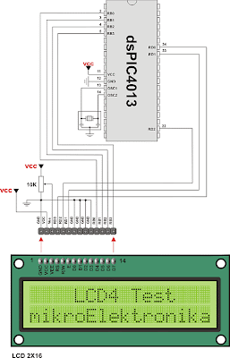
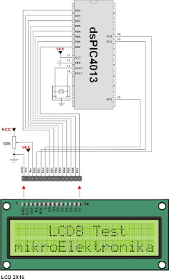
The following example 2x16 LCD connection (16characters, 2 line) to a dsPIC30F microcontroller by using a 4-bit and 8-bit interface. The following code demonstrates the usage of the LCD Custom Library routines. The example covers the initialization of the LCD module and instructions for contolling and writing the module. The realization is carried out by using the mikroBasic compiler for dsPIC30F Microcontrollers. The interconnection of the LCD module and a dsPIC30F devices by using a 4-bit interface is shown in Fig. 13-1.

Interface LCD 2 x 16 to  MicrocontrollerInterface LCD 2 x 16 to Microcontroller (dsPIC30F) using 4-bit

Interface LCD 2 x 16 to  MicrocontrollerInterface LCD 2 x 16 to Microcontroller (dsPIC30F) using 4-bit


example program LCD 4bit

dim txt as string[15]

main:
ADPCFG = $FFFF
Lcd_Init(PORTB, 3,2,1,0, PORTD, 0,2,1)
Lcd_Cmd(LCD_CURSOR_OFF)
Lcd_Cmd(LCD_CLEAR)

Lcd_Out(1, 1, "mikroElektronika")
Lcd_Out(2, 1, "2x16 LCD Testing")
end.


example program LCD 8bit

dim txt as string[10]

main:
ADPCFG = $FFFF ' PORTB to be digital
Lcd8_Init(PORTB, 7, 6, 5, 4, 3, 2, 1, 0, PORTD, 0, 1, 2)
Lcd8_Cmd(LCD_CURSOR_OFF)
Lcd8_Cmd(LCD_CLEAR)

Lcd8_Out(1, 1, "mikroElektronika")
Lcd8_Out(2, 1, "2x16 LCD Testing")
end.

Source

Wednesday, February 03, 2010

Datasheet LCD 2 x16 (HD44780U)

The HD44780U dot-matrix liquid crystal display controller and driver LSI displays alphanumerics, Japanese kana characters, and symbols. It can be configured to drive a dot-matrix liquid crystal display under the control of a 4- or 8-bit microprocessor. Since all the functions such as display RAM, character generator, and liquid crystal driver, required for driving a dot-matrix liquid crystal display are internally provided on one chip, a minimal system can be interfaced with this controller/driver.

A single HD44780U can display up to one 8-character line or two 8-character lines. The HD44780U has pin function compatibility with the HD44780S which allows the user to easily replace an LCD-II with an HD44780U. The HD44780U character generator ROM is extended to generate 208 5 ´ 8 dot character fonts and 32 5 ´ 10 dot character fonts for a total of 240 different character fonts. The low power supply (2.7V to 5.5V) of the HD44780U is suitable for any portable battery-driven product equiring low power dissipation.
LCD 2 x16 (HD44780U)

Specifications LCD 2x16 (HD44780U)
  • Characters: 2x16
  • Character Resolution: 5x7
  • Connection: Standard 16 PIN interface
  • Backlight: Green
  • Voltage Supply: 5V
  • Dimensions: 3.6 cm x 8 cm x 1 cm (H x W x D)

HD44780U Pin Connection
  • PIN 1: Vss - GND
  • PIN 2: VDD - +5V VCC
  • PIN 3: Vo - Contrast Adjustment
  • PIN 4: RS - Reset
  • PIN 5: R/W - Read/Write ("0" = Write to LCD module "1" = Read from LCD module)
  • PIN 6: E - Enable Signal
  • PIN 7: DB0 Data 0
  • PIN 8: DB1 Data 1
  • PIN 9: DB2 Data 2
  • PIN 10: DB3 Data 3
  • PIN 11: DB4 Data 4
  • PIN 12: DB5 Data 5
  • PIN 13: DB6 Data 6
  • PIN 14: DB7 Data 7
  • PIN 15: Backlight +5V VCC
  • PIN 16: Backlight GND

Table LCD HD44780U Instruction set

Table Characterset for 5x7 dot font

Monday, February 01, 2010

Datasheet LCD 4 Digits SP521PR

This 4 digits LCD SP521PR based digital thermometer, it is possible to measure from -40 to +150 degree celsius. It uses S8100 or 1S1588 as thermal sensor. The power consumption is very small and it is possible to operate about 3 months continuously from a 9-V cell.

This is the TN (Twisted Nematic)-type liquid crystal display. It is possible to 4 digits display but the display of the maximum figure is only "1". It isn't possible to work continuously in the direct current. However, when applying the about 5-V DC voltage between the backplane (common) and the terminal, the color of the segment which corresponds can be temporarily changed to the black. With this, the correspondence of the terminal and the display segment can be confirmed.

LCD 4 Digits SP521PRLCD 4 Digits SP521PR pic

note:

The maximum applied voltage : 10 V
The operating temperature : -10 to 55°C
The storage temperature : -20 to 60°C

When using the 5-V power supply, the resistor as much as 10K-ohm must be put in series to prevent from big electric current's flowing in case of the short circuit. The specification of SP521PR to be using this time is as follows.

Rangkaian Thermometer Digital

Thermometer Digital

At this thermometer circuit, the sensor (S8100) or diode (1S1588) is used as the thermo sensor. When using the IC thermo sensor, the thermometry to +100°C from -40°C is possible. Also, when using the diode, the measurement to +150°C from -20°C is possible. Both sensors are contained in the kit.

This time, the thermometer circuit used the diode as the thermo sensor to measure more than +100°C. ICL7136 is used for the thermometer and is measuring the change of the forward direction minute voltages of the diode by the temperature. The 3-1/2 digits liquid crystal display (SP521PR) is used for the display. The most significant digit can display only "1".

The consumption electric power of ICL7136 is very small and it is possible to operate about 3 months continuously with the 9-V cell.

Rangkaian thermometer digital Skema rangkaian thermometer digital

LCD SP521PR Pinning
Liquid crystal display (LCD) SP521PR Pinning


Specification of LCD SP521PR .

4 digits display
The letter height : 12.7 mm
The maximum applied voltage : 10 V
The operating temperature : -10 to 55°C

Note: When using the 5-V power supply, the resistor as much as 10K-ohm must be put in series to prevent from big electric current's flowing in case of the short circuit.