Kristal Tester
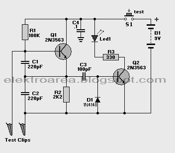
In the world of electronics using crystal oscilator almost always in use. In the circuit below is a series to test the crystal. (Not measuring frequensy). With this circuit we could find out whether the crystal is still good or not. Test Clip to attach electrodes on crystal (foot), S1 in the press (On) then LED1 will light up if the crystal is still good. if you mendapa difficulties 2N356U transistors can be used with the type of transistor NTE123AP / PN100 / 2N3904.
The mechanism of this crystal tester is very simple. If a good crystal is connected to the test lead, the oscillator will work, and an AC signal will be generated at Q1 emitter. This AC signal will flow through capacitor C3 and trigger the Q2 to light the LED indicator. The diode 1N4148 provide the back path for the AC signal. If the crystal is bad, the oscillator won’t work, and there is only DC voltage level at Q1 emitter. This DC voltage level won’t trigger the Q2 transistor since the capacitor C3 block any DC signal. You can use any high gain high frequency transistor for this crystal tester circuit, in case you can’t find exact transistor series as shown in the schematic diagram.
The mechanism of this crystal tester is very simple. If a good crystal is connected to the test lead, the oscillator will work, and an AC signal will be generated at Q1 emitter. This AC signal will flow through capacitor C3 and trigger the Q2 to light the LED indicator. The diode 1N4148 provide the back path for the AC signal. If the crystal is bad, the oscillator won’t work, and there is only DC voltage level at Q1 emitter. This DC voltage level won’t trigger the Q2 transistor since the capacitor C3 block any DC signal. You can use any high gain high frequency transistor for this crystal tester circuit, in case you can’t find exact transistor series as shown in the schematic diagram.


