Sunday, January 23, 2011

Rangkaian Alat Bantu Pendengaran

This circuit, connected to 32 Ohm impedance mini-earphones, can detect very remote sounds. Useful for theatre, cinema and lecture goers: every word will be clearly heard. You can also listen to your television set at a very low volume, avoiding to bother relatives and neighbors. Even if you have a faultless hearing, you may discover unexpected sounds using this device: a remote bird twittering will seem very close to you.

Rangkaian Alat Bantu PendengaranSkema Rangkaian Alat Bantu Pendengaran

The heart of the circuit is a constant-volume control amplifier. All the signals picked-up by the microphone are amplified at a constant level of about 1 Volt peak to peak. In this manner very low amplitude audio signals are highly amplified and high amplitude ones are limited. This operation is accomplished by Q3, modifying the bias of Q1 (hence its AC gain) by means of R2.
A noteworthy feature of this circuit is 1.5V battery operation.

List Component
P1        : 22K   Log. Potentiometer
R1,R9 : 10K
R2 : 1M
R3 : 4K7
R4,R7 : 100K
R5 : 3K9
R6 : 1K5
R8 : 100R
C1,C2 : 100nF
C3,C6 : 1µF/63V
C4 : 10µF/25V
C5 : 470µF/25V
D1 : 1N4148
Q1,Q2,Q3 : BC547
Q4 : BC337
MIC1 : electret microphone
SW1 : SPST Switch
J1 : Stereo 3mm. Jack socket
B1 : 1.5V Battery (AA or AAA cell etc.)
Circuit from: www.sound.westhost.com

READMORE...

Monday, January 10, 2011

30W Mini Mosfet Amplifier

This mini mosfet amplifier project was a sort of challenge: designing an audio amplifier capable of delivering a decent output power with a minimum parts count, without sacrificing quality. The Power Amplifier section employs only three transistors and a handful of resistors and capacitors in a shunt feedback configuration but can deliver more than 18W into 8 Ohm and up to 30W into a 4 Ohm load.

Rangkaian 30watt Mini Mosfet AmplifierSkema Rangkaian Mini Mosfet Amplifier

To obtain such a performance and to ensure overall stability of this very simple circuitry, a suitable regulated dc power supply is mandatory. This is not a snag because it also helps in keeping noise and hum of the preamp to very low levels and guarantees a predictable output power into different load impedances. Finally, as the amplifier requires only a single rail supply, a very good dc voltage regulator capable of supplying more than 2 Ampare/40V can be implemented with a few parts also.

How to Setup of this Amplifier Circuit
  • Connect the Power Supply Unit to the Power Amplifier
  • Rotate the cursor of R4 fully towards Q1 Collector.
  • Set the cursor of R3 to about the middle of its travel.
  • Connect a suitable loudspeaker or a 8 Ohm 20W resistor to the amplifier output.
  • Connect a Multimeter, set to measure about 50V fsd, across the positive end of C5 and the negative ground.
  • Switch on the supply and rotate R3 very slowly in order to read about 23V on the Multimeter display.
  • Switch off the supply, disconnect the Multimeter and reconnect it, set to measure at least 1Amp fsd, in series to the positive supply (the possible use of a second Multimeter in this place will be very welcomed).
  • Switch on the supply and rotate R4 very slowly until a reading of about 120mA is displayed.
  • Check again the voltage at the positive end of C5 and readjust R3 if necessary.
  • If R3 was readjusted, R4 will surely require some readjustment.
  • Wait about 15 minutes, watch if the current is varying and readjust if necessary.
  • 12. Please note that R3 and R4 are very sensitive: very small movements will cause rather high voltage or current variations, so be careful.
  • 13. Those lucky enough to reach an oscilloscope and a 1KHz sine wave generator, can drive the amplifier to the maximum output power and adjust R3 in order to obtain a symmetrical clipping of the sine wave displayed.
List Componet
R1    : 2K2  1/4W Resistor
R2 : 27K 1/4W Resistor
R3,R4 : 2K2 1/2W Trimmers Cermet or Carbon (or 2K)
R5 : 100R 1/4W Resistor
R6 : 1K 1/4W Resistor
R7,R8 : 330R 1/4W Resistors

C1 : 22µF/25V
C2 : 47pF/63V
C3,C4 : 100µF/50V
C5 : 2200µF/50V

Q1 : BC550C NPN Transistor
Q2 : IRF530 N-Channel Hexfet Transistor (or MTP12N10)
Q3 : IRF9530 P-Channel Hexfet Transistor (or MTP12P10)

Circuit From: www.redcircuits.com

READMORE...

9 Volt Portable Headphone Amplifier Circuit

Here I present a very simple and powerful headphone amplifier Circuit using NE5534/2 . In addition to the IC NE5534/2, the circuit uses only few passive components and can easily generate a lot of sound from even the most inefficient headphones and there will be no compromise for the quality.

9 Volt Headphone Amplifier Circuit Circuit of 9 Volt Portable Headphone Amplifier


The 5534/2 is a low-distortion, low-noise device, having also the ability to drive low-impedance loads to a full voltage swing while maintaining low distortion. Furthermore, it is fully output short-circuit proof. Therefore, this circuit was implemented with a single 5532 chip forming a pair of stereo, inverting amplifiers, having an ac gain of about 3.5 and capable of delivering up to 3.6V peak-to-peak into a 32 Ohm load (corresponding to 50mW RMS) at less than 0.025% total harmonic distortion (1kHz & 10kHz).

List Component of Portable Headphone Amplifier
P1 = 22K
R1 = 18K
R2 = 68K
R3 = 68K
R4 = 68K
R5 = 18K
R6 = 68K
C1 = 4.7uF/25v
C2 = 4.7uF/25v
C3 = 22pF
C4 = 220uF/25v
C5 = 220uF/25v
C6 = 4.7uF/25v
C7 = 22pF
C8 = 220uF/25v
J1 = 3.5mm Stereo Jack
B1 = 9V Alkaline Battery
IC1 = NE5532 or NE5534
SW1 = SPST Toggle Switch
Circuit From: www.redcircuits.com

READMORE...

Darlington Pair to Drive DC motor Circuit

A normal variable resistor cannot directly control the speed of a motor since motors draw large amounts of current which would burn out the potentiometer. Instead, the small amount of current that the potentiometer can pass can be amplified into order to run the motor. This amplification can be achieved using Darlington Pair of transistors.

Darlington Pair to Drive DC motor CircuitDarlington Pair to Drive DC motor Circuit

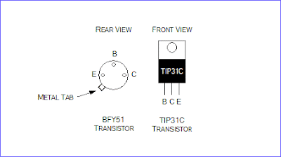
Pin-out BFY61 & TIP31C Transistor

The circuit above shows a linear potentiometer connected Between Vs and 0V Such That the voltage at its wiper terminal will of always be somewhere at or Between these two voltages. The small amount of current flowing out of the potentiometer's wiper is amplified by two transistors, connected together in a configuration known as a 'Darlington pair'. The current from the potentiometer is amplified by the first transistor, and then again by the second transistor, greatly Increasing the amount of current That cans be controlled by the potentiometer.

There are, however, a couple of disadvantages of this simple circuit. Firstly, about 0.7V is lost in EACH of the transistor, so the maximum voltage cans That ever be applied to the motor is Vs - 1.4V. Secondly, the transistors are not absolutely linear so the change in motor speed for a given rotation of the potentiometer will from some more subtle in the middle of its range. Because a motor is an inductive load, it will from Produce a 'back-emf' Could the which damage to the second transistor. The 1N4148 signal diode prevents this damage by shorting out the back-emf.

The power supply for this circuit should preferably be un-smoothed (i.e. directly from the power supply rectifier). This helps prevent the motor 'sticking' at low speeds. With the TIP31C transistor given, the maximum power supply voltage may be 60V and the maximum motor current consumption may be 3A.

Source: www.eleinmec.com

READMORE...

Rangkaian 8038 frequency | Signal Generator

frequency | Signal Generator circuit is a circuit that produces a variety of different waveforms at a desired frequency. It can generate Sine waves, Square waves, Triangular and Sawtooth waveforms as well as other types of output waveforms. There are many "off-the-shelf" waveform generator IC's available and all can be incorporated into a circuit to produce the different periodic waveforms.

Rangkaian 8038 frequency | Signal Generator Skema Rangkaian 8038 frequency | Signal Generator

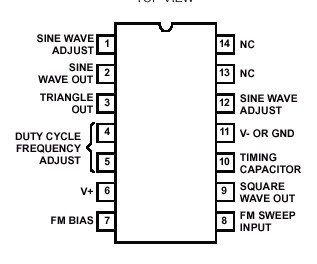
IC 8038 Pinout IC 8038 Pinout

One such device is the 8038 a precision waveform generator IC capable of producing sine, square and triangular output waveforms, with a minimum number of external components or adjustments. Its operating frequency range can be selected over eight decades of frequency, from 0.001Hz to 300kHz, by the correct choice of the external R-C components.

The frequency of oscillation is highly stable over a wide range of temperature and supply voltage changes and frequencies as high as 1MHz is possible. Each of the three basic waveform outputs, sine, triangle and square are simultaneously available from independent output terminals. The frequency range of the 8038 is voltage controllable but not a linear function. The triangle symmetry and hence the sine wave distortion are adjustable.

READMORE...

Sunday, January 09, 2011

Bistable Multivibrator Using IC 555 Circuit

555 Bistable Multivibrator circuit acts as a basic flip-flop. The Output will stable in two states: output high and output low. The switching of the output waveform is achieved by controlling the Trigger and Reset inputs which are held "HIGH" by the two pull-up resistors, R1 and R2. By taking the Trigger input (pin 2) "LOW", switch in Set position, changes the output state into the "HIGH" state and by taking the Reset input (pin 4) "LOW", switch in Reset position, changes the output into the "LOW" state. This 555 timer circuit will remain in either state indefinitely and is therefore bistable. Then the Bistable 555 timer is stable in both states, "HIGH" and "LOW".

555 Bistable Timer CircuitSkema Rangkaian 555 Bistable Multivibrator


Note:
  • Trigger (555 pin 2) makes the output high, Trigger is 'active low', it functions when <>
  • Reset (555 pin 4) makes the output low. Reset is 'active low', it resets when <>
  • The power-on reset, power-on trigger and edge-triggering circuits can all be used as described above for the

READMORE...

Saturday, January 08, 2011

IC 555 Monostable Circuit

Monostable circuit produces one pulse of a set length in response to a trigger input Such as a push button. The output of the circuit stays in the low state Until there is a trigger input, Hence the name "monostable" meaning "one stable state".

This type of circuit is ideal for use in a "push to operate" system for a model displayed at EXHIBITIONS. A visitor cans push a button to start a model's mechanism, moving, and the mechanism will from automatically switches off after a set time.

The circuit diagram of the 555 monostable circuit is given as follows.

Monostable Using IC 555 Circuit Monostable Using IC 555 Circuit

IC 555 Pinout

Note:
  • resistor value R and the capacitor value C are unspecified. The values of these components determine the length of time that the monostable output is in the high state, and they may be calculated using the equation below
  • T = 1.1RC or R = T/1.1C

In the monostable mode, the timer 555 acts as a "one-shot" pulse generator. The pulse Begins Pls the 555 timer receives a signal at the trigger input That falls below a third of the voltage supply. The width of the output pulse is determined by the time constant of an RC network, the which consists of a capacitor (C) and a resistor (R). The output pulse ends Pls the charge on the C equals 2 / 3 of the supply voltage. The output pulse width cans be lengthened or shortened to the need of the specific application by adjusting the values of R and C

READMORE...
 
Skema Rangkaian Elektronika