Wednesday, December 29, 2010

High Voltage Meter or Probe Design

Common voltmeters, digital or analog, usually range to some hundred volts maximum. Higher voltages not only cannot be indicated, but will also destroy the instrument. However, the range of any voltmeter can easily be extended using extra series resistance, as shown in the figure. Calculating the necessary resistance implies knowledge of the input impedance of the voltmeter.

High Voltage Meter or Probe Circui
Circuit and formula for constructing high voltage probes. For example, let's assume we want to extend the range of a standard digital voltmeter (input impedance 10MOhm) to 100kV. The maximum DC voltage the meter can take is 1000V. This means we need an external 1GOhm high voltage resistor in series with the meter. The total voltage ios given by the value indicatedby the meter, times 100. If we wanted to read the voltage in kV directly, we would need a resistor 1000 times as large as the input impedance of the voltmeter, i.e. 10GOhm.

Such home-brew high voltage probes are good for DC only. For AC voltages, capacitive input impedance of the meter and capacity of the probe must be matched, which is difficult to achieve because of parasitic capacitance of the resistor chain. A few pF (the capacitance of a 1cm radius metallic sphere) make a big difference, especially at higher frequencies.

Source: kronjaeger.com
READMORE...

Rangkaian Transistor Tester

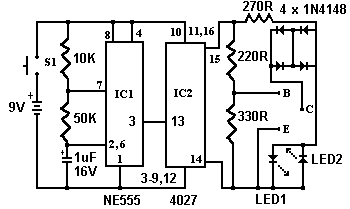
The circuit shown below is a simple circuit transistor tester. In some digital and analog avometer now mostly been contained this feature, but it can not hurt us a little more creative. This circuit can also be used to detect whether a transistor is NPN / PNP.

Rangkaian Transistor TesterSkema Rangkaian Transistor Tester

Circuit operation is as follows. The 555 timer is set up as a multi-vibrator 12hz. The output on pin 3 drives the 4027 flip-flop. This flip-flop divides the input frequency by two and delivers complementary voltage outputs to pin 15 and 14. The outputs are connected to LED1 and LED2 through the current limiting resistor R3. The LED's are Arranged so Pls That the polarity across the circuit is one way only one LED will from light and Pls the polarity reverses the other LED light earnest, therefore Pls no transistor is connected to the tester the LED's will from alternately flash. Also The 4027 outputs are connected to resistors R4 and R5 with the junction of these two resistors connected to the base of the transistor being tested. With a good transistor connected to the tester, the transistor will of turn on and Produce a short across the LED pair. If a good NPN transistor is connected then LED1 will from flash by Itself and if a good PNP transistor is connected then LED2 will from flash by Itself. If the transistor is open both LED's will from flash and if the transistor is shorted then neither LED will from flash.

IC NE555 PinoutIC NE555 Pinout

IC 4027 PinoutIC 4027 Pinout

READMORE...

Tuesday, December 28, 2010

Rangkaian Regulator Variable Sederhana

Regulator Variable Sederhana

A simple but less efficient method of controlling a DC voltage is to use a voltage divider and transistor emitter follower configuration. The figure below illustrates using a 1K pot to set the base voltage of a medium power NPN transistor.

Rangkaian Regulator Variable SederhanaSkema Rangkaian Regulator Variable Sederhana

The collector of the NPN feeds the base of a larger PNP power transistor which supplies most of the current to the load. The output voltage will be about 0.7 volts below the voltage of the wiper of the 1K pot so the output can be adjusted from 0 to the full supply voltage minus 0.7 volts. Using two transistors provides a current gain of around 1000 or more so that only a couple milliamps of current is drawn from the voltage divider to supply a couple amps of current at the output.

Note that this circuit is much less efficient than the 555 timer dimmer circuit using a variabe duty cycle switching approach. A fairly large heat sink is required to prevent the PNP power transistor from overheating. The advantage of the circuit is simplicity, and also that it doesn't generate any RF interference as a switching regulator does. The circuit can be used as a voltage regulator if the input voltage remains constant.

READMORE...

Simple switch-Off Time Delay Circuit

Designing a switch off delay circuit is quite simple and will cost you no more than $5 to make. All parts can be picked up from Radio Shack or Fry's if you have them as well as Parts Express. This will cover the mechanical aspects of it - theoretical topics can come later. If you suffer from pops on your amps or any other components, this will help you eliminate it, but it does not work in all cases.

Simple switch-Off Time Delay CircuitSimple switch-Off Time Delay Circuit

Designing a swictch off delay circuit is quite simple and will cost you no more than $5 to make. All parts can be picked up from Radio Shack or Fry's if you have them as well as Parts Express. This will cover the mechanical aspects of it - theoretical topics can come later. If you suffer from pops on your amps or any other components, this will help you eliminate it, but it does not work in all cases.

The two circuits di atas illustrate opening a relay contact a short time after the ignition or ligh switch is turned off. The capacitor is charged and the relay is closed when the voltage at the diode anode rises to 12 volts. The circuit on the left is a common collector or emitter follower and has the advantage of one less part since a resistor is not needed in series with the transistor base. However the voltage across the relay coil will be two diode drops less than the supply voltage, or about 11 volts for a 12.5 volt input. The common emitter configuration on the right offers the advantage of the full supply voltage across the load for most of the delay time, which makes the relay pull-in and drop-out voltages less of a concern but requires an extra resistor in series with transistor base. The common emitter (circuit on the right) is the better circuit since the series base resistor can be selected to obtain the desired delay time whereas the capacitor must be selected for the common collector (or an additional resistor used in parallel with the capacitor).

The time delay for the common emitter will be approximately 3 time constants or 3*R*C. The capacitor/resistor values can be worked out from the relay coil current and transistor gain. For example a 120 ohm relay coil will draw 100 mA at 12 volts and assumming a transistor gain of 30, the base current will be 100/30 = 3 mA. The voltage across the resistor will be the supply voltage minus two diode drops or 12-1.4 = 10.6. The resistor value will be the voltage/current = 10.6/0.003 = 3533 or about 3.6K. The capacitor value for a 15 second delay will be 15/3R = 1327 uF. We can use a standard 1000 uF capacitor and increase the resistor proportionally to get 15 seconds.

Source: bowdenshobbycircuits.info

READMORE...

Monday, December 27, 2010

Simple Switch On Time Delay Circuit

This Switch On Time Delay circuit has been designed to create a lamp switch operated electronically with an option of setting a delay in the time of execution of operation to reduce one or more lamps in a stairwell or any other places where this circuit may be useful. The circuit can be useful to control various lamp or appliances that can be connected in relay contacts.

Switch On Time Delay  CircuitSimple Switch On Time Delay Circuit

The circuit that takes advantage of the emitter/base breakdown voltage of an ordinary bi-polar transistor. The reverse connected emitter/base junction of a 2N3904 transistor is used as an 8 volt zener diode which creates a higher turn-on voltage for the Darlington connected transistor pair. Most any bi-polar transistor may be used, but the zener voltage will vary from about 6 to 9 volts depending on the particular transistor used. Time delay is roughly 7 seconds using a 47K resistor and 100uF capacitor and can be reduced by reducing the R or C values. Longer delays can be obtained with a larger capacitor, the timing resistor probably shouldn't be increased past 47K. This Switch On Time Delay circuit should work with most any 12 volt DC relay that has a coil resistance of 75 ohms or more. The 10K resistor connected across the supply provides a discharge path for the capacitor when power is turned off and is not needed if the power supply already has a bleeder resistor.

Sumber: http://www.bowdenshobbycircuits.info

READMORE...

9 Second Countdown Power-On Relay With 7 segment Display

9 Second Countdown Power-On Relay Circuit 9 Second Countdown Power-On Relay Circuit

This circuit provides a 9 second delay using a 7 segment display. When the switch is closed, the CD4010 up/down counter is preset to 9 and the 555 timer is disabled with the output held high. When the switch is opened, the timer produces an approximate 1 second clock signal, decrementing the counter until the 0 count is reached. When the zero count is reached, the 'carry out' signal at pin 7 of the counter moves low, energizing the 12 volt relay and stopping the clock with a low signal on the reset line (pin 4). The relay will remain energized until the switch is again closed, resetting the counter to 9. The 1 second clock signal from the 555 timer can be adjusted slightly longer or shorter by increasing or decreasing the resistor value at pin 3 of the timer.

Note:
  • The circuit can be powered from a 9V PP3 battery or 12V DC power supply.
  • The time delay can be varied by replace the resistor value at pin 3 IC555.
  • The push button switch is for starting the timer.
  • The appliance can be connected via contacts relay.

Source: bowdenshobbycircuits.info

READMORE...

Saturday, December 25, 2010

Driver Relay Menggunkan Transistor

Basic Transistor relay driver

Bipolar transistor is a component that works based on the presence or absence of flow in the foot triggers the base. In the relay driver applications, the transistor works as a switch that at the time did not accept the current triggers, then the transistor will be in the position of the cut-off and does not conduct current, Ic = 0. And when the base receives the flow triggers, then the transistor will turn into a state of saturation and delivers current. The following is a practical circuit of relay drivers that are reliable for use in microcontroller projects.

Rangkaian Driver Relay Menggunkan TransistorSkema Rangkaian Driver Relay
Menggunkan Transistor

The circuit on the left is a common collector or emitter follower and has the advantage of one less part since a resistor is not needed in series with the transistor base. However the voltage across the relay coil will be two diode drops less than the supply voltage, or about 11 volts for a 12.5 volt input.

The common emitter configuration on the right offers the advantage of the full supply voltage across the load for most of the delay time, which makes the relay pull-in and drop-out voltages less of a concern but requires an extra resistor in series with transistor base. The common emitter (circuit on the right) is the better circuit since the series base resistor can be selected to obtain the desired delay time whereas the capacitor must be selected for the common collector (or an additional resistor used in parallel with the capacitor).

The time delay for the common emitter will be approximately 3 time constants or 3*R*C. The capacitor/resistor values can be worked out from the relay coil current and transistor gain. For example a 120 ohm relay coil will draw 100 mA at 12 volts and assumming a transistor gain of 30, the base current will be 100/30 = 3 mA. The voltage across the resistor will be the supply voltage minus two diode drops or 12-1.4 = 10.6. The resistor value will be the voltage/current = 10.6/0.003 = 3533 or about 3.6K. The capacitor value for a 15 second delay will be 15/3R = 1327 uF. We can use a standard 1000 uF capacitor and increase the resistor proportionally to get 15 seconds.

Source: bowdenshobbycircuits.info

READMORE...

Saturday, December 18, 2010

Rangkaian Ampere Meter Digital

This is a circuit of a digital ampere meter with 4 digit LED 7-segment display, the circuit capable of measuring the current consumption up to 10A with selected 100mA, 10mA and 1mA accuracy, and consumes only about 25mA of current. The ammeter is based on single ICL7107 chip and 3.5-digit seven segment LED displays. Due to a Relatively small number of components That the circuit is using it is possible to fit it on a small 3cm x 7cm printed circuit board.

Rangkaian Ampere Meter DigitalSkema Rangkaian Ampere Meter Digital

0.01 Ohm resistor should be made out of 1.5mm thick / 5cm long copper wire. 0.1 Ohm and 1 Ohm resistors should have 5W ratings.

For highest accuracy it is recommended that the ICL7107 ampere meter module should be supplied with its own voltage supply. If measurement of the current of the same supply is needed, ICL7107 ampere meter would have to sample negative not positive voltage supply.

Brightness of the LED displays can be varied by adding or removing 1N4148 small signal diodes that are connected in series. Use two 1N4148 diodes for higher brightness.

Also, the use of 7805 5V voltage regulator is highly recommended to prevent the damage of ICL7107 and 7660 ICs. .

Source: http://electronics-diy.com

READMORE...

Power Meter Schematic For Audio Amplifier

This is a simple schematic of audio power meter using LM3915 IC, this schematic can be used to measure the actual output power of your amplifier. For an audio engineer, this schematic Seems to be very helpful, especially for checking of sound system installation and field testing. Due to its logarithmic scale, the wide range of audio output with only ten scales cans Also be measured. If you take an attention to the pin number 5 of the LM3915, see That you will from the input is not yet Rectified. At this input pin, the negative swing will from the present. However, it is harmless since the current is limited by R1, the LM3915 earnest therefore respond only to positive cycle.
Power Meter Schematic Schematic of Power Meter For Audio Amplifier

Note:
When the speaker resistance is 4Ω, then, make R1=10kΩ, if the resistance of speaker is 8Ω, make R1=8kΩ, and if the resistance of speaker is 16Ω, make R1=30kΩ.

The absence of peak detector or the detector will of averages give the circuit a fast reading of instantenous power, and this Gives us insight of both average and peak condition. For more readable peak or average mesurement, you cans use peak or average detector circuit.

source : national semiconductor application notes

READMORE...

Sound Level (Decibel) Meter Circuit

This is a decibel meter electronic circuit, For an audio engineer, this circuit seems to be very helpful, especially for checking of sound pressure levels from about 60 to 70 Decibel (dB). EACH light represents about a 3dB change in sound level so That Pls all three lights are on, the sound level is about 4 times Greater than the level needed to light one lamp. The sensitivity cans be adjusted with the 500K pot so That one lamp comes on with a reference sound level. The other two lamps will from then indicate about a 2X and 4X increase is in volume.
Sound Level (Decibel) Meter CircuitCircuit of Sound Level (Decibel) Meter

In operation, with no input, the DC voltage at pins 1,2 and 3 of the op-amp will be about 4 volts, and the voltage on the (+) inputs to the 3 comparators (pins 5,10,12) will be about a half volt less due to the 1N914 diode drop. The voltage on the (-) comparator inputs will be around 5.1 and 6.5 which is set by the 560 and 750 ohm resistors.

When an audio signal is present, the 10uF capacitor connected to the diode will charge toward the peak audio level at the op-amp output at pin 1. As the volume increases, the DC voltage on the capacitor and also (+) comparator inputs will increase and the lamp will turn on when the (+) input goes above the (-) input. As the volume decreases, the capacitor discharges through the parallel 100K resistor and the lamps go out. You can change the response time with a larger or smaller capacitor.

Source: www.bowdenshobbycircuits.info

READMORE...

Thursday, December 09, 2010

220V AC Operated Christmas Light Star Circuit

Here is a simple circuit of Christmas light star that can be easily constructed even by a novice. The main advantage of this circuit is that it doesn’t require any step-down transformer or ICs.
220V AC Operated Christmas Light Star CircuitCircuit of 220V AC Operated Christmas Light Star

Components like resistors R1 and R2, capacitors C1, C2, and C3, diodes D1 and D2, and zener ZD1 are used to develop a fairly steady 5V DC supply voltage that provides the required current to operate the multivibrator circuit and trigger triac BT136 via LED1. The multivibrator circuit is constructed using two BC548 transistors (T1 and T2) and some passive components. The frequency of the multivibrator circuit is controlled by capacitors C4 and C5 and resistors R3 through R7. The output of the multivibrator circuit is connected to transistor T3, which, in turn, drives the triac via LED1. During positive half cycles of the multivibrator’s output, transistor T3 energises triac BT136 and the lamp glows. This circuit is estimated to cost Rs 75.

Note:
This circuit directly connected to the netting of electricity, voltage 220V electricity it could sting you. Avoid working in damp and directly with ground

Circuit Design By: PRINCE PHILLIPS
Source: www.electronicsforu.com

READMORE...

220V AC Ultra Bright LEDs lamp Circuit

This ultra-bright white LED lamp works on 230V AC circuit with minimal power consumption. Ultra-bright LEDs available in the market cost Rs 8 to 15. These LEDs emit a 1000-6000mCd bright white light, like the welding arc and work on 3 volts, 10 mA. Their maximum voltage is 3.6 volts and the current is 25 mA. Anti-static precautions taken Pls Should Be handling the LEDs. The LEDs in a water-clear plastic package emit spotlight, while diffused type LEDs have a wide-angle radiation pattern.
220V AC Ultra Bright LEDs lamp Circuit220V AC Ultra Bright LEDs lamp Circuit

The schematics circuit of above employs capacitive reactance for limiting the current flow through the LEDs on the application of mains voltage to the circuit. We use only if a series resistor for limiting the current with mains operation. The 100-ohm, 2W resistor series avoids heavy 'inrush' During current transients. MOV at the input prevents surges or spikes, protecting the circuit. The 390-kilo-ohm, ½-watt resistor acts as a bleeder to Provide discharge path for capacitor Cx Pls mains supply is disconnected. The zener diode at the output section prevents excess levels of reverse voltage appearing across the LEDs During the negative half-cycles. During the positive half cycle, the voltage across the LEDs is limited to the zener voltage.
220V AC Ultra Bright LEDs lamp Circuit16-LED/46-LED combination

Aseries combination of 16 LEDs Gives a luminance (lux) equivalent of a 12W bulb. But if you have two series combinations of 23 LEDs in parallel (Total 46 LEDs), it Gives equal to a 35W light bulb.

Diode D1 (1N4007) and capacitor C1 act as rectifying and smoothing elements to Provide DC voltages to the row of LEDs. For a 16-LED row, use Cx of 12:22 μF, 630V; C1 of 22 μF, 100V; and zener of 48V, 1W. Similarly, for 46 LEDs combination use Cx of 0:47 mF, 630V; C1 of 33 μF, 150V; and zener of 69V, 1W. This circuit (inclusive of LEDs) costs Rs 200 to Rs 400.

Source

READMORE...

LTC4060 - NiMH/NiCd Battery Charger Circuit

This cheap and easy to build NiCd/NiMH Battery Charger circuit is suitable for automatically charging a wide range of batteries for many applications. This 'intelligent' charger was designed for high current and rapid charge applications such as cordless power tools and model racing cars. These battery packs are expensive and sometimes difficult to purchase. This charger uses the cell manufacturer's recommended charge method, to safely and quickly charge batteries.
Rangkaian NiMH/NiCd Battery ChargerSkema Rangkaian NiMH/NiCd Battery Charger

Linear Technology Corporation introduces the LTC4060, an autonomous 1- to 4-cell, 0.4A to 2A linear NiMH and NiCd battery charger. The LTC4060 includes all the functions required for a battery charger circuit. The design is simple and needs only three passive components. The LTC4060 also eliminates the need for a sense resistor and blocking diode, which increases efficiency and lowers the solution cost. This IC is targeted at applications including portable medical equipment, automotive diagnostic systems and industrial/telecom test devices.

The LTC4060 - NiMH/NiCd Battery Charger circuit Features
  • Complete Fast Charger Controller for Single, 2-, 3- or 4-Series Cell NiMH/NiCd Batteries
  • No Firmware or Microcontroller Required
  • Termination by –∆V, Maximum Voltage or Maximum Time
  • No Sense Resistor or Blocking Diode Required
  • Automatic Recharge Keeps Batteries Charged
  • Programmable Fast Charge Current: 0.4A to 2A
  • Accurate Charge Current: ±5% at 2A
  • Fast Charge Current Programmable Beyond 2A with External Sense Resistor
  • Automatic Detection of Battery
  • Precharge for Heavily Discharged Batteries
  • Optional Temperature Qualified Charging
  • Charge and AC Present Status Outputs Can Drive LED
  • Automatic Sleep Mode with Input Supply Removal
  • Negligible Battery Drain in Sleep Mode: <>
  • Manual Shutdown
  • Input Supply Range: 4.5V to 10V
  • Available in 16-Lead DFN and TSSOP Packages

READMORE...

Wednesday, December 08, 2010

Rangkaian 50Hz Accurate Oscillator

This circuit is a getting a 50Hz pulse. The oscillator circuit need only provide the IC ELM446, crystal and two appropriate loading capacitors
Rangkaian 50Hz Accurate OscillatorSkema Rangkaian 50Hz Accurate Oscillator
Note:
  • for greater accuracy as usual, it is also good practice to place a bypass capacitor across the power supply as well

The IC ELM446 is an 8 pin digital divider integrated circuit, that provides both 50Hz and 1Hz outputs from a common 3.58MHz NTSC colourburst crystal. Externally, the designer need only provide the crystal and two appropriate loading capacitors, as well as a suitably bypassed power supply. Internal Oscillator circuits then use this reference frequency to precisely derive a stable 50Hz signal. For convenience, a complementary 50Hz signal is also provided. This signal is then further divided to provide a 1Hz signal output. By ELM Electronics
IC ELM446This is pinout of IC ELM446, If you need more detail please download ELM446's pdf datasheet.

READMORE...

Microphone Condenser Pre Amplifier Circuit

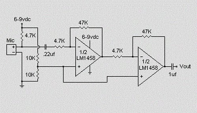
This is a simple preamplifier circuit for electret condenser microphone. using a LM1458 dual op amp IC. The circuit takes the audio signal rom the condenser microphone and amplifier it, so you can use the microphone as the input to some device which wouldn’t normally accept microphone level signals .
Electret condenser Preamplifier Circuit Schematic Circuit of Microphone Electret
Condenser Pre Amplifier

The circuit requires a 6-9 volt supply. Output of the microphone amplifier can be made variable by connecting a 10kΩ potentiometer . Circuit’s gain can be increased by men perbesar the value of 47K, depending on the input sensitivity of the main amplifier system. The microphone should be housed in a small round enclosure.

List componet of condenser pre-amp mic circuit
Q1,Q2    : LM1458 Op-Amp
R1,R2,R3 : 4.7k ohm resistor
R4, R5 : 10k ohm resistor
R6,R7 : 47k ohm resistor
C1, : 0.22uF ceramic capacitor
C2 : 1uF ceramic capacitor
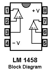
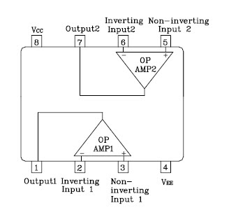
LM 1458 PinningAbsolute maximum ratings of LM 1458 IC
Supply Voltage               :  ±18V
Power Dissipation : 400 mW
Differential Input Voltage : ±30V
Input Voltage : ±15V
Output Short-Circuit Duration: Continuous
Operating Temperature Range : 0°C to +70°C
Storage Temperature Range : −65°C to +150°C
Lead Temperature :(Soldering, 10 sec.) 260°C

READMORE...

Tuesday, December 07, 2010

Mobile Phone Battery Charger Circuit

This Mobile phone chargers circuit presented here comes as a low-cost alternative to charge mobile telephones/battery packs.

Mobile Phone Battery Charger CircuitCircuit of Mobile Phone Battery Charger

The 220V AC mains supply is downconverted to 9V AC by transformer X1. The transformer output is rectified by diodes D1 through D4 wired in bridge configuration and the positive DC supply is directly connected to the charger’s output contact, while the negative terminal is connected through current limiting resistor R2. LED2 works as a power indicator with resistor R1 serving as the current limiter and LED3 indicates the charging status. During the charging period, about 3 volts drop occurs across resistor R2, which turns on LED3 through resistor R3. An external 12V DC supply sourcecan also be used to energise the charger, where resistor R4, after polarity protection diode D5, limits the input current to a safe value. The 3-terminal positive voltage regulator LM7806 (IC1) provides a constant voltage output of 7.8V DC since LED1 connected between the common terminal (pin 2) and ground rail of IC1 raises the output voltage to 7.8V DC. LED1 also serves as a power indicator for the external DC supply. After constructing the circuit on a veroboard, enclose it in a suitable cabinet. A small heat sink is recommended for IC1.

Circuit Design By: PRINCE PHILLIPS
Source: www.electronicsforu.com

READMORE...

Sunday, November 28, 2010

Rangkaian On/Off 24 Hours Timer

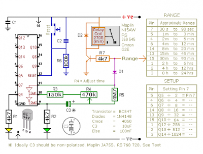
This is a circuits are multi-range timers offering periods of up to 24 hours and beyond. This circuit can be used as repeating timers - or as single-shot timers

Rangkaian On/Off 24 Hours TimerSkema Rangkaian On/Off 24 Hours Timer

The Cmos 4060 is a 14-bit binary counter. However - only ten of those bits are connected to output pins. The 4060 also has two inverters - connected in series across pins 11, 10 & 9. Together with R3, R4, R5 and C3 - they form a simple oscillator.

While the oscillator is running - the 14-bit counter counts the number of oscillations - and the state of the count is reflected in the output pins. By adjusting R4 you can alter the frequency of the oscillator. So you can control the speed at which the count progresses. In other words - you can decide how long it will take for any given output pin to go high.

When that pin goes high - it switches the transistor - and the transistor in turn operates the relay. In single-shot mode - the output pin does a second job. It uses D1 to disable the oscillator - so the count stops with the output pin high.

If you want to use the timer in repeating mode - simply leave out D1. The count will carry on indefinitely. And the output pin will continue to switch the transistor on and off - at the same regular time intervals.

Note:
  • Using "Trial and Error" to set a long time period would be very tedious. A better solution is to use the Setup tables provided - and calculate the time required for Pin 7 to go high. For example, if you want a period of 9 Hours - the Range table shows that you can use the output at Pin 2. You need Pin 2 to go high after 9 x 60 x 60 = 32 400 seconds. The Setup table tells you to divide this by 512 - giving about 63 seconds. Adjust R4 so that the Yellow LED lights 63 seconds after power is applied. This will give an output at Pin 2 after about 9 Hours.
  • Ideally C3 should be non-polarized - but a regular electrolytic will work - provided it doesn't leak too badly in the reverse direction. Alternatively - you can simulate a non-polarized 10uF capacitor by connecting two 22uF capacitors back to back
  • The timers were designed for a 12-volt supply. However - provided a suitable relay is used - both circuits will work at anything from 5 to 15-volts. Applying power starts the timer. And it can be reset at any time by a brief interruption of the power supply.
Sorcer: http://www.zen22142.zen.co.uk/

READMORE...

Wednesday, November 24, 2010

220 Volt Disco Lamp circuit

This disco lamp circuit is not a voice operated switch (VOX) because this circuit is too dumb to differentiate between musical sound or human voice. This is rather a sound activated than voice activated. One interesting application is to control your disco lighting automatically by the musical sound from high power amplifier, when the music signal is dominating the sound space. The disco lamp circuit schematic diagram is shown below.
220 Volt Disco Lamp circuit
You can use either moving coil microphone or condenser microphone for this circuit. Make sure the electrolytic capacitor is rated for 16 volt or more. The potentiometer shown in the schematic diagram is used to adjust the gain of the pre-amplification. You can adjust this potentiometer to get a proper sound level where the relay would be activated.

List Componet Of Disco Lamp circuit
  • R1 : 22k 1/4 watt resistor
  • R2 : 4K7 watt resistor
  • R3 : 2K2 watt resistor
  • R4,R8 : 10K watt resistor
  • R5 : 33K watt resistor
  • R6 : 56K watt resistor
  • R7 : 1M watt resistor
  • Potensio: 50K
  • C1 : 470uf/35V electrolytic capacitor
  • C2 : 22n ceramic capacitor
  • C3 : 100n ceramic capacitor
  • C4 : 1Uf/50V electrolyticcapacitor
  • D1 - D5 : 1N4007
  • D6 : Zener 5.1v
  • D7 : 1N4148
  • IC : CD 4069
  • SCR : FIR 3D
  • Mic : Mic Condensor

READMORE...

Megabass Circuit

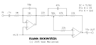
The following is megabass circuit schematic (rangkaian megabass) . The megabass circuit is a modified Baxandall tone control with no bass cut and no treble control. It boosts frequencies from about 30Hz to 160Hz can boost by 14dB.
Rangkaian megabass Skema Rangkaian megabass

Note:
  • The input capacitor can be replaced with a .01uf cap if you wish.
  • The 10pf capacitor is optional and will start rolling off everything over 15kHz. 5pf will double this to 31kHz.
  • The tone control requires a low impedence input. If you already have a low impedence input, the input buffer can be removed. However, the output is inverted.
  • The opamp is not critical. A 4558 would be just fine.
  • I do not show the parts for the +4.5 reference. Here is the +4.5 voltage divider I used.
IC A4558 Pinning IC A4558 Pinning

The A4558 is a monolithic Integrated Circuit designed for dual operational amplifier.

Absolute maximum ratings of A4558 Ap-amp
  • Supply voltage VCC 20 or ±10 V
  • Differential input voltage VIND 20 V
  • Input voltage VIN ±10 V
  • Power Dissipation PD 300 mW
  • Operating temperature Topr -45 ~ +85 °C
  • Storage temperature Tstg -55 ~ +150 °C

READMORE...

Saturday, November 20, 2010

Rangkaian Toggle Switch With Relay

This circuit will energize and de-energize a relay at the push of a button. Any type of momentary action push-to-make switch can be used. Pushing the button once - will energize the relay. And pushing it a second time - will de-energize the relay

Rangkaian Toggle Switch Skema Rangkaian Toggle Switch

I've drawn the circuit with a single pole relay. But you can use a multi-pole relay if it suits your application. Only one half of the Cmos 4013 is used. So you could construct two independent toggle switches with a single IC. The circuit will work at anything from 5 to 15-volts. All you need do is select a relay with a coil voltage that suits your supply.

The LED provides a visual indication that the relay is energized. In effect - it tells you whether the switch is on or off. It's not necessary to the operation of the circuit. If you wish you may leave out R3 and the LED.

Source: http://www.zen22142.zen

READMORE...

IC 555 Motorcycle Alarm Circuit

Rangkaian Motorcycle Alarm

This circuit features an intermittent siren output and automatic reset. It can be operated manually using a key-switch or a hidden switch; but it can also be wired to set itself automatically when you turn-off the ignition. By adding external relays you can immobilize the bike, flash the lights etc. I have used Andy's Asymmetric Timer as the basis for this design.

Rangkaian Motorcycle AlarmSkema Rangkaian IC 555 Motorcycle Alarm

Any number of normally-open switches may be used. Fit "tilt" switches that close when the steering is moved or when the bike is lifted off its side-stand or pushed forward off its centre-stand. Use micro-switches to protect removable panels and the lids of panniers etc.

The alarm's standby current is virtually zero - so it won't drain your battery. Once activated - the rate at which the siren switches on and off is controlled by R7, R8 & C4. For example, increasing R7 will make the sound period longer - while increasing R8 gives longer silent periods.

The circuit is designed to use an electronic Siren drawing 300 to 400mA. It's not usually a good idea to use the bike's own Horn because it can be easily located and disconnected. However - if you choose to use the Horn - remember that the alarm relay is too small to carry the necessary current. Connect the coil of a suitably rated relay to the "Siren" output. This can then be used to sound the Horn, flash the lights etc.

The circuit board and switches must be protected from the elements. Dampness or condensation will cause malfunction. Connect a 1-amp in-line fuse AS CLOSE AS POSSIBLE to your power source. This is VERY IMPORTANT. The fuse is there to protect the wiring - not the alarm. Exactly how the system is fitted will depend on the make of your particular machine - so I'm unable to provide any further help or advice in this regard.

When you set the alarm - if one of the switches is closed - the siren will sound. This could cause annoyance late at night. A small modification will allow you to Monitor The State Of The Switches using LEDs. When the LEDs are all off - the switches are all open - and it's safe to turn the alarm on


Source: http://www.zen22142.zen

READMORE...

Friday, November 12, 2010

600 Watt Darlington Power Amplifier Circuit

This Power amplifier circuit is based around IC audio power amplifier driver (LM4702) manufactured by NATIONAL and darlington power transistors MJ11029 - MJ11028 by ON semiconductors
Rangkaian 600 Watt Darlington Power AmplifierRangkaian 600 Watt
Darlington Power Amplifier


Note:
  • Recommended power supply voltage : 30V to 35V
  • Max power supply voltage : 45V

This Power amplifier circuit produces output power up to 300 watts ( 8ohms) pada masing-masing channelnya. It is a high fidelity audio power amplifier. Designed for demanding consumer and pro-audio applications. You can also use this circuit with AV receivers, Audiophile power amps, Pro Audio High voltage industrial applications etc

Amplifier output power maybe scaled by changing the supply voltage and number of output devices. The circuit includes thermal shutdown circuitry that activates when the die temperature exceeds 150. CIRCUIT mute function, when activated, mutes the input drive signal and forces the amplifier output to a quiescent state.

IC audio power amplifier driver
(LM4707) Pinning

READMORE...

Thursday, November 11, 2010

10-Band Graphic Equalizer Circuit Diagram

This circuit allows you to equlize the audio signals in 10 band. It uses low amount op-amps (TL074 - JFET op-amp) to anatomy a able blaster circuit. The affection of the architecture is a classical band-pass alive filter. The VCC is in ambit of 12 ~ 15 VDC and The VDD is in ambit of -12 ~ -15 VDC respectively.
Rangkaian 10 band graphic equalizer Skema rangkaian 10-band
graphic equalizer

Note:
For more details the circuit scheme, click on the picture

As shown in the diagram, there are 10 same units that only differ in capacitance values of capacitors which determine the frequency band of each filter. The potentiometers adjust the predetermined regions of frequency in each unit.

The components must be high quality and have low tolerance, Specifically potesometer RV1... the 10 and capacitors.. The resistors must be metal-film type.

If it is intended for stereo use then it will be supposed it is made in two pieces with as much as possible suited the materials, between the channels, so that do not exist differences in the regulation of each band frequencies.

Switch S1 isolates the circuit EQ, when him we did not need and it ensures level [ flat ] response in the exit of circuit. The circuit should be connected between preamplifier and in a final power amplifier.

Component list of graphic equalizer circuit
  • R1-R20= 10Kohms
  • R21-R40= 1Mohms
  • R41-R10Kohms
  • R42= 1Kohms
  • R43-R52= 2.2Kohms
  • R53-R62= 47Kohms
  • R63-64-66-67= 47Kohms
  • R65= 10Kohms
  • R68-69= 47 ohms 1/2W
  • RV1-RV10= 100Kohms lin FADER
  • RV11= 10Kohms log.
  • C1= 180nF polyester
  • C2= 18nF polyester
  • C3= 100nF polyester
  • C4= 10nF polyester
  • C5= 47nF polyester
  • C6= 4.7nF polyester
  • C7= 22nF polyester
  • C8= 2.2nF polyester
  • C9= 12nF polyester
  • C10= 1.2nF polyester
  • C11= 5.6nF polyester
  • C12= 560pF polysterine
  • C13= 2.7nF polyester
  • C14= 270pF polysterine
  • C15= 1.5nF polyester
  • C16= 150pF polysterine
  • C17= 680pF polysterine
  • C18= 68pF polysterine
  • C19= 360pF polysterine
  • C20= 36pF polysterine
  • C21= 4.7uF polyester
  • C22-23= 33pF polysterine
  • C24= 10uF 25V
  • C25,C26= 47uF 25V
  • C27-C32= 47nF polyester
  • IC1-IC3= TL074
  • S1= 2X4 SW for stereo

READMORE...

Thursday, October 28, 2010

Rangkaian 12VDC Fluorescent Lamp Driver

Whenever there is a need for battery-powered lighting, like for camping, solar powered cottages, cars, boats, planes, or emergency purposes, fluorescent lamps have a great appeal. Firstly, they are very much more efficient than glow lamps, so they produce much more light for less power consumption. Secondly, their light color stays constant while the battery runs down.

In this article I will offer driver circuit for 12 V/5Watt fluorescent lamp, this circuit used a normal 220 to 10V stepdown transformer in reverse to step 12V to about 240V to drive a lamp without the need to warm the filaments.
Rangkaian 12VDC Fluorescent Lamp DriverSkema Rangkaian 12VDC Fluorescent Lamp Driver

Note:
  • Q1 (IRF510 MOSFET) must be installed on a heat sink
  • Dangerous ...!! Please be careful, This series contains 220 VAC that can sting you.

The IC1 TLC 555 is wired as an astable multivibrator for producing the necessary oscillations.The MOSFET Q1 is used to amplify the oscillations produced by the IC1.The out put of MOSFET is connected to the primary of the step up transformer to produce a ~240 V AC for driving the florescent lamp.

List Component:
  • C1 100uf /25V Electrolytic Capacitor
  • C2,C3 100nf Ceramic Capacitor
  • C4 100nf /1KV Ceramic Capacitor
  • R1 1K Resistor
  • R2 2.7K Resistor
  • Q1 IRF510 MOSFET
  • U1 TLC555 Timer IC
  • T1 300mA, 10V/220v Transformer
  • LAMP 5W Fluorescent Lamp
  • MISC Board, Wire, Heatsink For Q1

READMORE...

Wednesday, October 27, 2010

Rangkaian Lampu LED Untuk Motor (12 Volt Battery)

Lampu LED Untuk Motor


Lamp type LED has several advantages compared with the usual light when the applied on a motorcycle.
In addition to more efficient battery when compared with normal hologen lamps, LED also has several other advantages, such as light more evenly and provide a luxurious feel to the vehicle.


The following are examples of simple creations that you can apply to decorate your motorcycle using the LED.
Lampu LED Untuk MotorRangkaian Lampu LED Untuk Motor

For this circuit is recommended only as a replacement motorcycle brake lights or city lights with the electrical source from the battery. Indeed in the market has many available variations of LED lights that can be used as brake lights or disco lights, but maybe some people would be proud if his own creative, hopefully circuit schemes that we present above can assist you in creating.

The following examples of applications that we apply to motorcycles mio


Lampu LED Untuk Motor

READMORE...

Monday, October 18, 2010

Rangkaian 220V Lamp Flasher

The 220V Lamp Flasher circuit basically is a line powered flasher which can be used in many applications such as the Chritmas lamp. Below is the circuit schematic diagram


Skema Rangkaian 220V Lamp Flasher

Note:
  • Input supply - 6 ~ 12 VDC
  • Output - upto 200 W lamp / bulb load
  • Optically isolated Mains supply
  • Onboard preset to adjust the frequency (speed) of flashing (1 Hz to 5 Hz)
  • Power Battery Terminal (PBT) for easy input 230 VAC mains and load connection
  • Terminal pins for connecting DC power supply
  • Four mounting holes of 3.2 mm each
  • List Componet of 220V Lamp Flasher circuit
  • CN1: 6 V to 12 VDC voltage source
  • C1: 10uF/25V capacitor elektrolit
  • C2: 0.22uF/275V capacitor elektrolit
  • C3: 47uF/25V capacitor elektrolit
  • C4: 0.1uF/25V capacitor elektrolit
  • D1: LED
  • D2, D3: 1N4148 Dioda
  • PR1: 100K Variable resistor
  • PR2: 50K Variable resistor
  • Q1: TIC226 Triac
  • R1: 2k2 resistor 1/2 watt
  • R2, R5: 1K resistor 1/2 watt
  • R3: 180E resistor 1/2 watt
  • R4: 680E resistor 1/2 watt
  • U1: LM555 IC timer
  • U2: MOC3021
  • V1: 230V AC input
  • Z1: 100W Load
Dangerous...!!
This circuit directly connected to the netting of electricity, voltage 220V electricity it could sting you. Avoid working in damp and directly with ground

READMORE...

Monday, September 27, 2010

Rangkaian Radar Pompa Air (Kontrol Ketinggian Air)

Radar Pompa Air (Kontrol Ketinggian Air)

By means of a Relay, employed to drive a water pump, this circuit provides automatic level control of a water reservoir or well.
Skema Rangkaian Radar Pompa air


Note:
  • The two steel rods must be supported by a small insulated (wooden or plastic) board.
  • The circuit can be used also with non-metal tanks, provided a third steel rod having about the same height of the tank will be added and connected to the circuit's negative ground.
The shorter steel rod is the "water high" sensor, whereas the longer is the "water low" sensor. When the water level is below both sensors, IC1C output (pin #10) is low; if the water becomes in contact with the longer sensor the output remains low until the shorter sensor is reached. At this point IC1C output goes high, Q1 conducts, the Relay is energized and the pump starts operating.

Now, the water level begins to decrease and the shorter sensor will be no longer in contact with the water, but IC1C output will be hold high by the signal return to pin #5 of IC1B, so the pump will continue its operation. But when the water level falls below the longer sensor, IC1C output goes low and the pump will stop.

SW1 is optional and was added to provide reverse operation. Switching SW1 in order to connect R3 to pin #11 of IC1D, the pump will operate when the reservoir is nearly empty and will stop when the reservoir is full. In this case, the pump will be used to fill the reservoir and not to empty it as in the default operating mode.

List Component
  • R1,R2: 15K 1/4W Resistors
  • R3: 10K 1/4W Resistor
  • R4: 1K 1/4W Resistor
  • D1: LED
  • D2: 1N4148 Diode
  • IC1: 4001
  • Q1: BC337 NPN Transistor
  • SW1: witch
  • RL1: Relay with SPDT 2A @ 230V switch, Coil Voltage 12V

READMORE...

Wednesday, September 01, 2010

Rangkaian ON OFF Sleep Timer Switch

ON/OFF Sleep Timer Switch

This timer was designed mainly to switch off a portable radio after some time: in this way, one can fall asleep on the sand or on a hammock, resting assured that the receiver will switch off automatically after some time, saving battery costs.

Rangkaian ON OFF Sleep Timer SwitchSkema Rangkaian ON OFF Sleep Timer Switch

R1 and C1 provide a very long time constant. When P2 is momentarily closed, C1 discharges and the near zero voltage at its positive lead is applied to the high impedance inputs of the four gates of IC1 wired in parallel. The four paralleled gate outputs of the IC go therefore to the high state and the battery voltage is available at Q1 Emitter. When P2 is released, C1 starts charging slowly through R1 and when the voltage at its positive lead has reached about half the battery voltage, the IC gate outputs fall to zero, stopping Q1. This transistor can directly drive a portable radio receiver or different devices drawing a current up to about 250mA. Connecting a Relay across the Emitter of Q1 and negative ground, devices requiring much higher voltage and current operation can be driven through its contacts.

Pushing on P2 for 1 to 5 seconds, the circuit starts and then will switch off after about 35 minutes. This time delay can be varied by changing R1 and/or C1 values. P1 will stop the timer if required. LED D1 is optional and can be useful to signal relay operation when the load is placed far from the timer.

List Component
  • R1: 10M 1/4W Resistor
  • R2: 4K7 1/4W Resistor
  • R3: 1K 1/4W Resistor
  • C1: 220µF/ 25V Electrolytic capacitor
  • D1: LED
  • D2: 1N4148
  • IC1: 4011 Quad 2 Input NAND Gate CMos IC
  • Q1: BC337
  • P1,P2: SPST Pushbuttons
  • RL1: 12V Relay
Source

READMORE...

Tuesday, August 31, 2010

Skema Dancing LEDs, Following the Rhythm of Music

Dancing LEDs

The basic circuit illuminates up to ten LEDs in sequence, following the rhythm of music or speech picked-up by a small microphone. The expanded version can drive up to ten strips, formed by up to five LEDs each, at 9V supply.

Rangkaian Dancing LEDsSkema Rangkaian Dancing LEDs

IC1A amplifies about 100 times the audio signal picked-up by the microphone and drives IC1B acting as peak-voltage detector. Its output peaks are synchronous with the peaks of the input signal and clock IC2, a ring decade counter capable of driving up to ten LEDs in sequence.
An additional circuit allows the driving of up to ten strips, made up by five LEDs each (max.), at 9V supply. It is formed by a 10mA constant current source (Q1 & Q2) common to all LED strips and by a switching transistor (Q3), driving a strip obtained from 2 to 5 series-connected LEDs. Therefore one transistor and its Base resistor are required to drive each of the strips used.

List Component of Dancing LEDs Circuit
  • R1: 10K 1/4W Resistor
  • R2,R3: 47K 1/4W Resistors
  • R4: 1K 1/4W Resistor
  • R5,R6,R7: 100K 1/4W Resistors
  • R8: 820R 1/4W Resistor
  • C1,C3: 100nF/63V Ceramic or Polyester Capacitors
  • C2: 10µF/50V Electrolytic Capacitor
  • C4: 330nF/63V Polyester Capacitor
  • C5: 100µF/25V Electrolytic Capacitor
  • D1: 1N4148
  • D2-D11: LEDs (any type and color)
  • IC1: LM358
  • IC2: 4017
  • M1: electret microphone
  • SW1: SPST Switch
  • B1: 9V PP3 Battery
Additional circuit parts:
  • R9,R10: 10K 1/4W Resistors
  • R11: 56R 1/4W Resistor
  • D12,D13 etc.: LEDs (any type and color)
  • Q1,Q2: BC327
  • Q3: BC337
Note:
  • The sensitivity of the circuit can be varied changing R4 value.
  • C4 value can be varied from 220 to 470nF in order to change the circuit speed-response to music peaks.
  • Adopting the additional circuit, only one item for R10, R11, Q1 and Q2 is required to drive up to ten LED strips. On the contrary, one item of R9 and Q3 is necessary to drive each of the strips you decided to use.
  • Each R9 input must be connected to IC2 output pins, in place of the LEDs D2-D11 shown. R8 must also be omitted.
  • Whishing to use a lower number of LEDs or LED strips, pin #15 of IC2 must be disconnected from ground and connected to the first unused output pin.
  • For example: if you decided to use 5 LEDs, pin #15 of IC2 must be connected to pin #1; if you decided to use 8 LEDs, pin #15 of IC2 must be connected to pin #9 etc.
  • Current drawing of the circuit is about 10mA.
  • Whishing to use a wall-plug adapter instead of a 9V battery, you can supply the circuit at 12V, allowing the use of up to 6 LEDs per strip, or at 15V, allowing the use of up to 7 LEDs per strip.
Source

READMORE...

Monday, August 23, 2010

Rangkaian LED 220VAC Sebagai Lampu Penerangan

The LED has advantages over other lighting technology. LED supposedly can hold up to 100,000 hours. This means that if the LED light 24 hours a day he would hold for 10 years. Whereas Fluorencent lights are usually only able to survive 1-3 years.

This is a modified version of the circuit, Super bright LED Night Light published that can directly connect to the netting PLN (220VAC).

rangkaian LED 220VACSkema rangkaian LED 220VAC

rangkaian LED 220VAC
Note:
Dangerous...!! this circuit directly connected to the netting of electricity, voltage 220V electricity it could sting you. Avoid working in damp and directly with ground

This is the circuit of a well tried and reliable 230-volt AC mains operated 24 LEDs (super bright LEDs 50mA). While Practically compare the brightness Between this and 11watts tube circuit, the LED light is much better. The layout is made in such a way, you get uniform Illumination. A photographs of the cicuit is Also given in this post.

READMORE...

Friday, August 20, 2010

Rangkaian Speaker Protector sederhana

Speaker Protector sederhana

This circuit follows will connects the speakers to the power amplifier output only a few seconds after the amplifier is powered ON, so that the speakers do not accept popped up by a high voltage and you would not Hear a loud thud sound from the speakers When the amplifier is switched on. This stuff is very harmful to the speakers.

Rangkaian Speaker Protector sederhanaSkema rangkaian speaker protector

When the amplifier is powered on the bridge D1 also gets powered through the amplifier’s power switch. Capacitor C1 filters the output of bridge rectifier D1. When the power switch is made ON, the transistor Q1 gets switched ON only after the capacitor C2 is sufficiently charged (0.7V) through the resistor R1. Here the value of C2 and R1 are so selected that the time delay is around 2 seconds. So the relay gets activated only after a few seconds the amplifier is powered ON and until that time the speaker will be kept isolated from the amplifier’s audio output as the speaker is connected to the amplifier’s output through the N/O contact of the relay. During this initial delay period the output of amplifier will be grounded by the resistor R2 through the N/C contact of the relay. This is done in order to ensure that the DC blocking capacitor at the amplifier’s output is charged before it is connected to the speaker.

Rangkaian Speaker Protector sederhanaBetter quality speaker protector Circuit

READMORE...

Sunday, August 15, 2010

Rangkaian Magnetic proximity sensors

Here is the circuit diagram of a magnetic proximity switch sensor which can be used in various applications. The circuit is based on a magnetic reed switch as the proximity sensor. A monostable multivibrator based on NE555 and a toggle flip flop CD4013 does the rest of the circuit.

rangkaian magnetic proximity sensors  Skema rangkaian magnetic proximity sensors
magnetic reed switch magnetic reed switch sensor

The magnetic proximity switch sensor circuit, in principle, consists of a reed switch at its heart. When a magnet is brought in the vicinity of the reed switch it operates and controls the rest of the switching circuit. In place of the reed switch, one may, as well, use a general-purpose electromagnetic reed relay as the sensor, if required. These tiny reed relays are easily available as they are widely used in telecom products. The reed switch or relay to be used with this circuit should be the normally open type.

When a magnet is brought in the vicinity of the sensor element for a moment, the contacts of the reed switch close to trigger timer IC1 wired in monostable mode. As a consequence its output at pin 3 goes high for a short duration and supplies clock to the clock input (pin 3 CD4013). LED D2 is used as a response indicator.

This CMOS IC2 consists of two independent flip-flops though here only one is used. Note that the flip-flop is wired in toggle mode with data input (pin 5) connected to the Q (pin 2) output. On receipt of clock pulse, the Q output changes from low to high state and due to this the relay driver transistor T1 gets forward-biased. As a result the relay RL1 is energised.

READMORE...

Saturday, August 14, 2010

Rangkaian Audio Channel Selector Stereo

Audio Channel Selector

This circuit serves for connecting the stereo outputs from Four Different channels as inputs and only one of Them is selected to the output at any one time.

When the circuit switch on, channel A (AR and AL) is selected. If no audio is present in channel A, the circuit Waits for Some time and then Selects the next channel (channel B). This search operation continues Until it detects an audio signal in one of the channels. The inter-channel delay time or the wait Can be adjusted with the help of preset VR1. If still longer time is needed, May replace one capacitor C1 with of higher value.

To manually skip over from one active channel to another active channel, simply push the skip switch (S1), until the desired channel input gets selected. The selected channel (A, B, C, or D) is indicated by the glowing of corresponding LED (LED11, 12, 13, or 14 ).

Rangkaian Audio Channel Selector  Stereo  Skema rangkaian audio channel selector stereo


IC CD4066 contains 4 analog switches, These switches are connected to four separate channels. These analogue switches are controlled by IC CD4017 outputs. CD4017 is a 10-bit ring counter IC. Since only one of its outputs is high at any instant, only one switch will be closed at a time. IC CD4017 is configured as a 4-bit ring counter by connecting the fifth output Q4 (pin 10) to the reset pin. Capacitor C5 in conjunction with resistor R6 forms a power-on-reset circuit for IC2, so that on initial switching on of the power supply, output Q0 (pin 3) is always high . The clock signal to CD4017 is provided by IC1 NE555 which acts as an astable multivibrator when transistor T1 is in cut- off state.

IC5 KA2281 is used here for not only indicating the audio levels of the selected stereo channel, but also for forward biasing transistor T1. As soon as a specific threshold audio level is detected in a selected channel, pin 7 and/or pin 10 of IC5 goes low . This low level is coupled to the base of transistor T1, through diode-resistor combination of D2-R1/D3-R22. As a result, transistor T1 conducts and causes output of IC1 to remain low as long as the selected channel output exceeds the preset audio threshold level.

Presets VR2 and VR3 have been included for adjustment of individual audio threshold levels of left and right stereo channels, as desired. Once the multivibrator action of IC1 is disabled, output of IC2 does not change further. Hence, searching through the channels continues until it receives an audio signal exceeding the preset threshold value. The skip switch S1 is used to skip a channel even if audio is present in the selected channel. The number of channels can be easily extended up to ten, by using additional 4066 ICs.

READMORE...
 
Skema Rangkaian Elektronika