Sunday, November 28, 2010

Rangkaian On/Off 24 Hours Timer

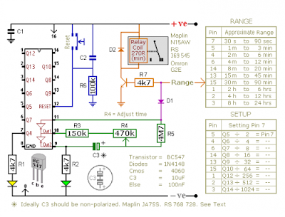
This is a circuits are multi-range timers offering periods of up to 24 hours and beyond. This circuit can be used as repeating timers - or as single-shot timers

Rangkaian On/Off 24 Hours TimerSkema Rangkaian On/Off 24 Hours Timer

The Cmos 4060 is a 14-bit binary counter. However - only ten of those bits are connected to output pins. The 4060 also has two inverters - connected in series across pins 11, 10 & 9. Together with R3, R4, R5 and C3 - they form a simple oscillator.

While the oscillator is running - the 14-bit counter counts the number of oscillations - and the state of the count is reflected in the output pins. By adjusting R4 you can alter the frequency of the oscillator. So you can control the speed at which the count progresses. In other words - you can decide how long it will take for any given output pin to go high.

When that pin goes high - it switches the transistor - and the transistor in turn operates the relay. In single-shot mode - the output pin does a second job. It uses D1 to disable the oscillator - so the count stops with the output pin high.

If you want to use the timer in repeating mode - simply leave out D1. The count will carry on indefinitely. And the output pin will continue to switch the transistor on and off - at the same regular time intervals.

Note:
  • Using "Trial and Error" to set a long time period would be very tedious. A better solution is to use the Setup tables provided - and calculate the time required for Pin 7 to go high. For example, if you want a period of 9 Hours - the Range table shows that you can use the output at Pin 2. You need Pin 2 to go high after 9 x 60 x 60 = 32 400 seconds. The Setup table tells you to divide this by 512 - giving about 63 seconds. Adjust R4 so that the Yellow LED lights 63 seconds after power is applied. This will give an output at Pin 2 after about 9 Hours.
  • Ideally C3 should be non-polarized - but a regular electrolytic will work - provided it doesn't leak too badly in the reverse direction. Alternatively - you can simulate a non-polarized 10uF capacitor by connecting two 22uF capacitors back to back
  • The timers were designed for a 12-volt supply. However - provided a suitable relay is used - both circuits will work at anything from 5 to 15-volts. Applying power starts the timer. And it can be reset at any time by a brief interruption of the power supply.
Sorcer: http://www.zen22142.zen.co.uk/

READMORE...

Wednesday, November 24, 2010

220 Volt Disco Lamp circuit

This disco lamp circuit is not a voice operated switch (VOX) because this circuit is too dumb to differentiate between musical sound or human voice. This is rather a sound activated than voice activated. One interesting application is to control your disco lighting automatically by the musical sound from high power amplifier, when the music signal is dominating the sound space. The disco lamp circuit schematic diagram is shown below.
220 Volt Disco Lamp circuit
You can use either moving coil microphone or condenser microphone for this circuit. Make sure the electrolytic capacitor is rated for 16 volt or more. The potentiometer shown in the schematic diagram is used to adjust the gain of the pre-amplification. You can adjust this potentiometer to get a proper sound level where the relay would be activated.

List Componet Of Disco Lamp circuit
  • R1 : 22k 1/4 watt resistor
  • R2 : 4K7 watt resistor
  • R3 : 2K2 watt resistor
  • R4,R8 : 10K watt resistor
  • R5 : 33K watt resistor
  • R6 : 56K watt resistor
  • R7 : 1M watt resistor
  • Potensio: 50K
  • C1 : 470uf/35V electrolytic capacitor
  • C2 : 22n ceramic capacitor
  • C3 : 100n ceramic capacitor
  • C4 : 1Uf/50V electrolyticcapacitor
  • D1 - D5 : 1N4007
  • D6 : Zener 5.1v
  • D7 : 1N4148
  • IC : CD 4069
  • SCR : FIR 3D
  • Mic : Mic Condensor

READMORE...

Megabass Circuit

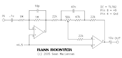
The following is megabass circuit schematic (rangkaian megabass) . The megabass circuit is a modified Baxandall tone control with no bass cut and no treble control. It boosts frequencies from about 30Hz to 160Hz can boost by 14dB.
Rangkaian megabass Skema Rangkaian megabass

Note:
  • The input capacitor can be replaced with a .01uf cap if you wish.
  • The 10pf capacitor is optional and will start rolling off everything over 15kHz. 5pf will double this to 31kHz.
  • The tone control requires a low impedence input. If you already have a low impedence input, the input buffer can be removed. However, the output is inverted.
  • The opamp is not critical. A 4558 would be just fine.
  • I do not show the parts for the +4.5 reference. Here is the +4.5 voltage divider I used.
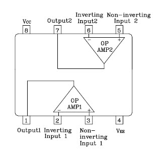
IC A4558 Pinning IC A4558 Pinning

The A4558 is a monolithic Integrated Circuit designed for dual operational amplifier.

Absolute maximum ratings of A4558 Ap-amp
  • Supply voltage VCC 20 or ±10 V
  • Differential input voltage VIND 20 V
  • Input voltage VIN ±10 V
  • Power Dissipation PD 300 mW
  • Operating temperature Topr -45 ~ +85 °C
  • Storage temperature Tstg -55 ~ +150 °C

READMORE...

Saturday, November 20, 2010

Rangkaian Toggle Switch With Relay

This circuit will energize and de-energize a relay at the push of a button. Any type of momentary action push-to-make switch can be used. Pushing the button once - will energize the relay. And pushing it a second time - will de-energize the relay

Rangkaian Toggle Switch Skema Rangkaian Toggle Switch

I've drawn the circuit with a single pole relay. But you can use a multi-pole relay if it suits your application. Only one half of the Cmos 4013 is used. So you could construct two independent toggle switches with a single IC. The circuit will work at anything from 5 to 15-volts. All you need do is select a relay with a coil voltage that suits your supply.

The LED provides a visual indication that the relay is energized. In effect - it tells you whether the switch is on or off. It's not necessary to the operation of the circuit. If you wish you may leave out R3 and the LED.

Source: http://www.zen22142.zen

READMORE...

IC 555 Motorcycle Alarm Circuit

Rangkaian Motorcycle Alarm

This circuit features an intermittent siren output and automatic reset. It can be operated manually using a key-switch or a hidden switch; but it can also be wired to set itself automatically when you turn-off the ignition. By adding external relays you can immobilize the bike, flash the lights etc. I have used Andy's Asymmetric Timer as the basis for this design.

Rangkaian Motorcycle AlarmSkema Rangkaian IC 555 Motorcycle Alarm

Any number of normally-open switches may be used. Fit "tilt" switches that close when the steering is moved or when the bike is lifted off its side-stand or pushed forward off its centre-stand. Use micro-switches to protect removable panels and the lids of panniers etc.

The alarm's standby current is virtually zero - so it won't drain your battery. Once activated - the rate at which the siren switches on and off is controlled by R7, R8 & C4. For example, increasing R7 will make the sound period longer - while increasing R8 gives longer silent periods.

The circuit is designed to use an electronic Siren drawing 300 to 400mA. It's not usually a good idea to use the bike's own Horn because it can be easily located and disconnected. However - if you choose to use the Horn - remember that the alarm relay is too small to carry the necessary current. Connect the coil of a suitably rated relay to the "Siren" output. This can then be used to sound the Horn, flash the lights etc.

The circuit board and switches must be protected from the elements. Dampness or condensation will cause malfunction. Connect a 1-amp in-line fuse AS CLOSE AS POSSIBLE to your power source. This is VERY IMPORTANT. The fuse is there to protect the wiring - not the alarm. Exactly how the system is fitted will depend on the make of your particular machine - so I'm unable to provide any further help or advice in this regard.

When you set the alarm - if one of the switches is closed - the siren will sound. This could cause annoyance late at night. A small modification will allow you to Monitor The State Of The Switches using LEDs. When the LEDs are all off - the switches are all open - and it's safe to turn the alarm on


Source: http://www.zen22142.zen

READMORE...

Friday, November 12, 2010

600 Watt Darlington Power Amplifier Circuit

This Power amplifier circuit is based around IC audio power amplifier driver (LM4702) manufactured by NATIONAL and darlington power transistors MJ11029 - MJ11028 by ON semiconductors
Rangkaian 600 Watt Darlington Power AmplifierRangkaian 600 Watt
Darlington Power Amplifier


Note:
  • Recommended power supply voltage : 30V to 35V
  • Max power supply voltage : 45V

This Power amplifier circuit produces output power up to 300 watts ( 8ohms) pada masing-masing channelnya. It is a high fidelity audio power amplifier. Designed for demanding consumer and pro-audio applications. You can also use this circuit with AV receivers, Audiophile power amps, Pro Audio High voltage industrial applications etc

Amplifier output power maybe scaled by changing the supply voltage and number of output devices. The circuit includes thermal shutdown circuitry that activates when the die temperature exceeds 150. CIRCUIT mute function, when activated, mutes the input drive signal and forces the amplifier output to a quiescent state.

IC audio power amplifier driver
(LM4707) Pinning

READMORE...

Thursday, November 11, 2010

10-Band Graphic Equalizer Circuit Diagram

This circuit allows you to equlize the audio signals in 10 band. It uses low amount op-amps (TL074 - JFET op-amp) to anatomy a able blaster circuit. The affection of the architecture is a classical band-pass alive filter. The VCC is in ambit of 12 ~ 15 VDC and The VDD is in ambit of -12 ~ -15 VDC respectively.
Rangkaian 10 band graphic equalizer Skema rangkaian 10-band
graphic equalizer

Note:
For more details the circuit scheme, click on the picture

As shown in the diagram, there are 10 same units that only differ in capacitance values of capacitors which determine the frequency band of each filter. The potentiometers adjust the predetermined regions of frequency in each unit.

The components must be high quality and have low tolerance, Specifically potesometer RV1... the 10 and capacitors.. The resistors must be metal-film type.

If it is intended for stereo use then it will be supposed it is made in two pieces with as much as possible suited the materials, between the channels, so that do not exist differences in the regulation of each band frequencies.

Switch S1 isolates the circuit EQ, when him we did not need and it ensures level [ flat ] response in the exit of circuit. The circuit should be connected between preamplifier and in a final power amplifier.

Component list of graphic equalizer circuit
  • R1-R20= 10Kohms
  • R21-R40= 1Mohms
  • R41-R10Kohms
  • R42= 1Kohms
  • R43-R52= 2.2Kohms
  • R53-R62= 47Kohms
  • R63-64-66-67= 47Kohms
  • R65= 10Kohms
  • R68-69= 47 ohms 1/2W
  • RV1-RV10= 100Kohms lin FADER
  • RV11= 10Kohms log.
  • C1= 180nF polyester
  • C2= 18nF polyester
  • C3= 100nF polyester
  • C4= 10nF polyester
  • C5= 47nF polyester
  • C6= 4.7nF polyester
  • C7= 22nF polyester
  • C8= 2.2nF polyester
  • C9= 12nF polyester
  • C10= 1.2nF polyester
  • C11= 5.6nF polyester
  • C12= 560pF polysterine
  • C13= 2.7nF polyester
  • C14= 270pF polysterine
  • C15= 1.5nF polyester
  • C16= 150pF polysterine
  • C17= 680pF polysterine
  • C18= 68pF polysterine
  • C19= 360pF polysterine
  • C20= 36pF polysterine
  • C21= 4.7uF polyester
  • C22-23= 33pF polysterine
  • C24= 10uF 25V
  • C25,C26= 47uF 25V
  • C27-C32= 47nF polyester
  • IC1-IC3= TL074
  • S1= 2X4 SW for stereo

READMORE...
 
Skema Rangkaian Elektronika