Wednesday, December 29, 2010

High Voltage Meter or Probe Design

Common voltmeters, digital or analog, usually range to some hundred volts maximum. Higher voltages not only cannot be indicated, but will also destroy the instrument. However, the range of any voltmeter can easily be extended using extra series resistance, as shown in the figure. Calculating the necessary resistance implies knowledge of...
READMORE...

Rangkaian Transistor Tester

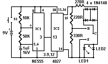
The circuit shown below is a simple circuit transistor tester. In some digital and analog avometer now mostly been contained this feature, but it can not hurt us a little more creative. This circuit can also be used to detect whether a transistor is NPN / PNP.Skema Rangkaian Transistor TesterCircuit operation is as follows. The 555 timer...
READMORE...

Tuesday, December 28, 2010

Rangkaian Regulator Variable Sederhana

Regulator Variable SederhanaA simple but less efficient method of controlling a DC voltage is to use a voltage divider and transistor emitter follower configuration. The figure below illustrates using a 1K pot to set the base voltage of a medium power NPN transistor.Skema Rangkaian Regulator Variable SederhanaThe collector of the NPN feeds...
READMORE...

Simple switch-Off Time Delay Circuit

Designing a switch off delay circuit is quite simple and will cost you no more than $5 to make. All parts can be picked up from Radio Shack or Fry's if you have them as well as Parts Express. This will cover the mechanical aspects of it - theoretical topics can come later. If you suffer from pops on your amps or any other components, this...
READMORE...

Monday, December 27, 2010

Simple Switch On Time Delay Circuit

This Switch On Time Delay circuit has been designed to create a lamp switch operated electronically with an option of setting a delay in the time of execution of operation to reduce one or more lamps in a stairwell or any other places where this circuit may be useful. The circuit can be useful to control various lamp or appliances that...
READMORE...

9 Second Countdown Power-On Relay With 7 segment Display

9 Second Countdown Power-On Relay CircuitThis circuit provides a 9 second delay using a 7 segment display. When the switch is closed, the CD4010 up/down counter is preset to 9 and the 555 timer is disabled with the output held high. When the switch is opened, the timer produces an approximate 1 second clock signal, decrementing the counter...
READMORE...

Saturday, December 25, 2010

Driver Relay Menggunkan Transistor

Basic Transistor relay driver Bipolar transistor is a component that works based on the presence or absence of flow in the foot triggers the base. In the relay driver applications, the transistor works as a switch that at the time did not accept the current triggers, then the transistor will be in the position of the cut-off and does not...
READMORE...

Saturday, December 18, 2010

Rangkaian Ampere Meter Digital

This is a circuit of a digital ampere meter with 4 digit LED 7-segment display, the circuit capable of measuring the current consumption up to 10A with selected 100mA, 10mA and 1mA accuracy, and consumes only about 25mA of current. The ammeter is based on single ICL7107 chip and 3.5-digit seven segment LED displays. Due to a Relatively...
READMORE...

Power Meter Schematic For Audio Amplifier

This is a simple schematic of audio power meter using LM3915 IC, this schematic can be used to measure the actual output power of your amplifier. For an audio engineer, this schematic Seems to be very helpful, especially for checking of sound system installation and field testing. Due to its logarithmic scale, the wide range of audio...
READMORE...

Sound Level (Decibel) Meter Circuit

This is a decibel meter electronic circuit, For an audio engineer, this circuit seems to be very helpful, especially for checking of sound pressure levels from about 60 to 70 Decibel (dB). EACH light represents about a 3dB change in sound level so That Pls all three lights are on, the sound level is about 4 times Greater than the level...
READMORE...

Thursday, December 09, 2010

220V AC Operated Christmas Light Star Circuit

Here is a simple circuit of Christmas light star that can be easily constructed even by a novice. The main advantage of this circuit is that it doesn’t require any step-down transformer or ICs.Circuit of 220V AC Operated Christmas Light StarComponents like resistors R1 and R2, capacitors C1, C2, and C3, diodes D1 and D2, and zener ZD1 are...
READMORE...

220V AC Ultra Bright LEDs lamp Circuit

This ultra-bright white LED lamp works on 230V AC circuit with minimal power consumption. Ultra-bright LEDs available in the market cost Rs 8 to 15. These LEDs emit a 1000-6000mCd bright white light, like the welding arc and work on 3 volts, 10 mA. Their maximum voltage is 3.6 volts and the current is 25 mA. Anti-static precautions taken...
READMORE...

LTC4060 - NiMH/NiCd Battery Charger Circuit

This cheap and easy to build NiCd/NiMH Battery Charger circuit is suitable for automatically charging a wide range of batteries for many applications. This 'intelligent' charger was designed for high current and rapid charge applications such as cordless power tools and model racing cars. These battery packs are expensive and sometimes difficult...
READMORE...

Wednesday, December 08, 2010

Rangkaian 50Hz Accurate Oscillator

This circuit is a getting a 50Hz pulse. The oscillator circuit need only provide the IC ELM446, crystal and two appropriate loading capacitorsSkema Rangkaian 50Hz Accurate OscillatorNote: for greater accuracy as usual, it is also good practice to place a bypass capacitor across the power supply as well The IC ELM446 is an 8 pin digital divider...
READMORE...

Microphone Condenser Pre Amplifier Circuit

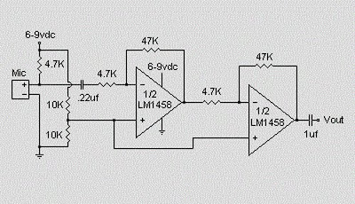
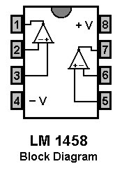
This is a simple preamplifier circuit for electret condenser microphone. using a LM1458 dual op amp IC. The circuit takes the audio signal rom the condenser microphone and amplifier it, so you can use the microphone as the input to some device which wouldn’t normally accept microphone level signals . Schematic Circuit of Microphone ElectretCondenser...
READMORE...

Tuesday, December 07, 2010

Mobile Phone Battery Charger Circuit

This Mobile phone chargers circuit presented here comes as a low-cost alternative to charge mobile telephones/battery packs.Circuit of Mobile Phone Battery Charger The 220V AC mains supply is downconverted to 9V AC by transformer X1. The transformer output is rectified by diodes D1 through D4 wired in bridge configuration and the positive...
READMORE...
 
Skema Rangkaian Elektronika