Showing posts with label Seven Segmen. Show all posts

Thursday, March 18, 2010

74LS47|Decoder BCD 4-bit to Seven Segment

Decoder BCD 4-bit to Seven Segment

decoder is a logic integrated circuit which serves to show the binary codes into signals that can be responded to visual. In accordance with a variety of ways encoding, then one can find various types of decoder, which one of them to the channel decoder output BCD seven segment

Types of BCD decoder into seven segments there are two kinds namely: which decoder functions for driving seven segment common anode mode, and decoder that functions for driving seven segment common cathode mode. but in this post we only present the common cathode mode decoder using IC 74LS47. The 74LS47 is usually used to display data from counter IC which then displayed on the seven segments.

The IC 74LS47 Feature active-low outputs designed for driving common-anode seven segment leds. The Schematic diagram of the 74LS47 is used to control the seven segments in the show on the image below

Rangkaian Decoder BCD 4-bit  to Seven Segment 74LS47Skema Rangkaian Decoder BCD 4-bit to Seven Segment 74LS47


Note:
  • (BI’) must be hight “1” when output function 0 throuht 15 are desired. The (RBI’) must be hight “1” if blanking of decimal zero is not desired.
  • When (BI’) low “0” all segment outputs are off regardless of the omy other input
  • (RBI’) adn input (ABCD) are low “0” with the lamp test hight, all segment outputs go off
  • (BI/RBO’) hight and a low is applied to the lamp-test input, all segment outputa are on
for more details you can using the truth table of the IC 74LS47

READMORE...

Monday, March 15, 2010

Rangkaian Decoder Seven Segmen 5 Bit

This decoder circuit also serves to change the 5-bit binary numbers to decimal to be displayed by seven segments. This decoder has a 5 pin input PA, PB, PC, PD PE and 14 pin output marked a, b, c, d, e, f and g.

For example, if the input PA, PB, PC, PD, PE = 11 01 0, then after the translated by the decoder will produce numbers a, b, c, d, e, f, g (MSD) = 10 0 1 1 1 1 and a, b, c, d, e, f, g (LSB) = 0 0 1 0 0 1 0. These numbers indicate that the negative pole (cathode) of the LED in a particular segment of a low voltage bias (0) so that the lights forming the number "12" on the seven-segment display devices. For more details can be seen in the picture

Rangkaian Decoder Seven Segmen 5 BitRangkaian Decoder Seven Segmen 5 Bit

In the circuit above using Seven Segment (7 Segment ) commond anode type. The principle works is, if the input pin Seven Segment a, b, c, d, e, f, g given voltage 0 volts, the LED on the Seven Segment props will be forward biased and turned to form a specific figure.

The seven segments can also be supplied with higher voltage (up to 18 V) but you have to replace the R 22 ohm with a greater value; morever, a suitable mast Rext be Chosen

Here is the truth table of the IC TDA4092 decoder

Absolute maximum rating IC TDA4092
  • Supply voltage…………….... 10 V
  • Input voltage……………….. .10 V
  • Off state output voltage…...... 20 V
  • Output current………………. 22 V
  • Total power dissipation ….. ... 0.8 mW
  • Storage and junction storage… -25 to 150 C
  • Operating temperature………. 0 to 70 C

READMORE...

Sunday, July 26, 2009

Rangkaian Antarmuka Seven Segmen Dengan AT89S51/52

Data that is processed mikrokontroler data hexa, to be shown on seven segment we can use dekoder hexa to the sevent segment or through the conversion program, for konveri, we can use the system look up table program we need a conversion table, table is as follows:

Place the module with mikrokontroler seven segment connecting module on port 1 and 3, do not look up inverted. Seven segment that is in use CA (Common Anode), thus need to be given to set the logic 0.
Antarmuka Seven Segmen-AT89S51/52Scheme of the Seven-segment

Antarmuka Seven Segmen-AT89S51/52The Switch scheme Electronics

Antarmuka Seven Segmen-AT89S51/52
;=================================================
;PROGRAM To turn 4X 7SEGMENT COMMON ANODA
;=================================================
ORG 00H
MULAI:
MOV P1,#0C7H ;display, data 0
CLR P3.4 ;Turn on COMMON 1
CALL DELAY ;Delay
SETB P3.4 ; turn off COMMON 1
CALL DELAY ;Delay
MOV P1,#040H ;display, data 1
CLR P3.5
CALL DELAY
SETB P3.5
CALL DELAY
MOV P1,#042H ;display, data 2
CLR P3.6
CALL DELAY
SETB P3.6
CALL DELAY
MOV P1,#050H ;display, data 3
CLR P3.7
CALL DELAY
SETB P3.7
CALL DELAY
AJMP MULAI
DELAY: ;Pause THIS USED 7SEGMENT To be invisibl
MOV R1,#1
DELAY1: DJNZ R0,$
DJNZ R1,DELAY1
RET
END

READMORE...

Saturday, July 25, 2009

Seven Segment


Seven Segment is 8 pieces of LED array is arranged in such a way that was shaping up to 7 segments and 1 point that can be used to show the pattern numbers and some letters. there are two types of seven-segment LED Seven segment of the Common Anode (CA) and Common Cathode (CC).

Seven Segment


On picture above is the layout, naming seven segment each segment and 8 illustrate the fruit is packed as the LED array LED Common Anoda (CA) and an array of LED Common Cathode (CC).
segemen seven controllers can be done directly, or through a pattern such as a driver IC 74LS47 to seven segment CA and 74LS48 to seven segment CC.

To save power it is, the LED does not continuously switched on the frequency of 85Hz to 100Hz. How this can be applied to the output enable series of flow control as AC generators, either sine, square, triangle or trapesium. But rarely on the set of digital more often use the AC current wave form of a square, it This is because the series of digital only have 2 types of condition (logic 0 and logic 1) and simulate the process square wave can be easily carried out, namely the exchange of a logic 1 to logic 0 periodically at a certain frequency.


READMORE...

Thursday, July 02, 2009

Rangkaian game 7-segmen

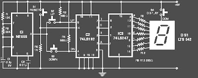
Rangkaian game  7-segmen

Skema Rangkaian game 7-segmen

You can play this game alone or with your friends. The circuit comprises a timer IC, two meters of decade and a driver of posting with a posting of segment 7. The play is simple. Like city above, it is a play of marking and the competitor which marks 100 points quickly (in short stages) is gaining it. To mark, one with the option to press the S2 switch or S3. Commutate S2, once pressed, realize against counting in the direction forwards, whereas the S3 switch helps to count in bottom. Before beginning a fresh play, and for this matter even a fresh movement, you must press on the S1 switch to give to zero the circuit. Then, press on the two switches the ones of, C. - with-D. S2 or S3. On pressing on the switch S2 or S3, the exits of the BCD of the meter change very quickly and when you release the switch, last remainders of number locked with the output of IC2. The locked number of BCD entered the BCD to the decoder of 7 segments/au conducting IC3 which leads a posting DIS1 of common-anode. However, you can read this number only when you press on the S4 switch. The order of the operations to play the (Rangkaian game 7-segmen) game enters, indicate that the `X of two players and Y, are recapitulated below:

  • The `X of player starts by pressing temporary contact STRONG CURRENT S1 followed by pressing and release of the S2 switch or S3. Then it supports on the S4 switch to read posting (points) and of the notes in bottom of this number (known as X1) manually.
  • The `Y of player also starts by pressing temporary S1 switch followed by the pressing of the S2 switch or S3 and note then in bottom of its points (known as Y1), after having pressed on the S4 switch, exactly of the same mode as made by the first player.
  • The `X of player still presses on the S1 switch and repeats the stages shown in stage 1 above and the notes in bottom of its new points (said, X2). He adds these points to his preceding points. The same process is repeated by the `Y of player in his turn.
  • The play continues up to the points reached by one of the two totals of players until or exceeds 100, to be declared as gaining.
  • Several players can take part in this play, with each one which obtains a chance to mark during its own turn. The assembly can be made using a universal council. Fix posting (LED and posting of segment 7) on the box with the three switches. The supply voltage for the circuit is 5V

READMORE...

Rangkaian Volt Meter Digital sederhana


Digital voltmeters are instruments that measure voltage or voltage drop in a circuit. They use solid-state components and display values digitally. Typically, digital voltmeters (digital volt meters) are used to locate excessive resistance that may indicate an open circuit or ground. They are also used to identify low voltage or voltage drops that may indicate a poor connection. Digital voltmeters are connected in parallel (and never in series) with the circuit being tested so that the meter can tap a small amount of current. The positive lead is connected to the circuits positive side and the negative lead is connected to the circuits ground. The digital voltmeters internal resistance is the impedance, which is usually expressed in ohms per volt. This amount is relatively high in order to prevent the device from drawing significant current and disturbing the operation of the circuit being tested. The sensitivity of the current meter and the value of the series resistance determine the range of voltages that digital voltmeters can measure.

Digital voltmeters can measure a range of alternating current (AC) voltages, direct current (DC) voltages, or both AC and DC voltages. Devices typically display between three and seven digits. Some digital voltmeters can capture minimum and maximum voltages called spike readings.

In the picture below is a series of simple digital voltmeter using the Seven-segment display, this series based ICL7107.The ICL7107 is a 3 1 / 2 digit LED A / D convertor. It contains an internal voltage reference, high isolation Switches analog, sequential control logic, and the display drivers. The auto-zero adjust ensures zero reading for 0 volts input.
Rangakaian Voltmeter digitalGambar skema Rangkaian Voltmeter digital

READMORE...
 
Skema Rangkaian Elektronika