Friday, September 11, 2009

Rangkaian 100watt Inverter 2N3055

This is a 100 Watt inverter circuit using minimum number of components. Here circuit used IC CD 4047 IC from Texas Instruments for generating the 100 Hz pulses and four 2N3055 transistors for driving the load.

IC1 Cd4047 wired as an astable multivibrator produces two 180 degree out of phase 100 Hz pulse trains. These pulse trains are are preamplifes by the two TIP122 transistors. The out puts of the TIP 122 transistors are amplified by four 2N 3055 transistors (two transistors for each half cycle) to drive the inverter transformer. The 220V AC will be available at the secondary of the transformer.Nothing complex just the elementary inverter principle and the circuit works great for small loads like a few bulbs or fans.If you need just a low cost inverter in the region of 100 W,then this is the best.

Inverter 100watt

Skema Rangkaian Inverter 100watt 2N3055


The maximum allowed output power of an inverter depends on two factors.The maximum current rating of the transformer primary and the current rating of the driving transistors, For example ,to get a 100 Watt output using 12 V car battery the primary current will be ~8A ,(100/12) because P=VxI.So the primary of transformer must be rated above 8A. Also here ,each final driver transistors must be rated above 4A. Here two will be conducting parallel in each half cycle, so I=8/2 = 4A .


Note:

  • A 12 V car battery can be used as the 12V source.
  • Use the POT R1 to set the output frequency to50Hz.
  • For the transformer get a 9-0-9 V , 10A step down transformer.But here the 9-0-9 V winding will be the primary and 220V winding will be the secondary.

IC CD4047 Description


IC CD4047


IC CD4047B is capable of operating in either the monostable or astable mode. It requires an external capacitor (between pins 1 and 3) and an external resistor (between pins 2 and
3) to determine the output pulse width in the monostable mode, and the output frequency in the astable mode. Astable operation is enabled by a high level on the astable input or low level on the astable input. The output frequency (at 50% duty cycle) at Q and Q outputs is determined by the
timing components. A frequency twice that of Q is available at the Oscillator Output; a 50% duty cycle is not guaranteed. Monostable operation is obtained when the device is triggered
by low-to-high transition at a trigger input or high-tolow transition at b trigger input. The device can be retriggered by applying a simultaneous low-to-high transition to both the a trigger and retrigger inputs. A high level on Reset input resets the outputs Q to low, Q to
high.

READMORE...

Thursday, September 10, 2009

Control Kecapatan Fan-Metode PWM

The following circuit is a circuit that is used to adjust the fan speed by using the PWM (Pulse Width Modulation). This circuit is very easy to make, and do not use the microcontroller or other digital components, for more details, let's look at his series of pictures below

Control Kecapatan FanSkema Rangkain Control Kecapatan Fan-Metode PWM


VR1: 10K Potentiometer Function as the motor speed control.

R9: Resistor as a determinant of minimum speed. Diseri with 10K VR, R1 for 1K will provide the settings range from 0 - 100% better used if the load used is a motor or a lamp. If R1 for 10K, will provide the range 5V - 12V is suitable if the load used is the cooling fan.

Q1: For 600mA maximum load, we recommend using the 2N2222A transistors packed in a metal body (TO-18). To load up to 5A please try using a transistor TIP120, 121 or 122.

D1: Diode is used to prevent back-emf which usually occurs in the load inductor such as Fan or Motor. Back-emf can damage the transistor!


Lay out PCD pic
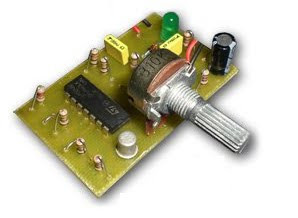
Finished Rangkaian Control Kecapatan Fan


Description IC The LM124 Low Power Quad Operational Amplifier

The LM124 series consists of four independent, high gain, internally frequency compensated operational amplifiers which were designed specifically to operate from a single power supply over a wide range of voltages. Operation from split power supplies is also possible and the low power supply current drain is independent of the magnitude of the power supply voltage.

Application areas include transducer amplifiers, DC gain blocks and all the conventional op amp circuits which now can be more easily implemented in single power supply systems. For example, the LM124 series can be directly operated off of the standard +5V power supply voltage which is used in digital systems and will easily provide the required interface electronics without requiring the additional ±15V power supplies.


READMORE...

Pengisi Battery Li-On Menggunakan USB

USB port it is one of the most useful port. Besides being used as an interface port for the device I / O computer, this port was also used as a filler Li-On Battery (Li-On Battery Charger). Battery charger circuit Li-On can you see in the image below


Pengisi BatterySkema Rangkaian Pengisi Battery Li-On

USB port capable of supplying a maximum voltage 5.25 V with a maximum flow of 0.5 A. Therefore, the above series can only be used to fill a Li-On Battery only. As LM3622 controller IC is used. IC's main function is as decisive end and a battery charging.


IC lm3622 Description

The LM3622 is a charge controller for Lithium-Ion batteries. This monolithic integrated circuit accurately controls an external pass transistor for precision Lithium-Ion battery charging. The LM3622 provides a constant voltage or constant current (CVCC) configuration that changes, as necessary, to optimally charge lithium-ion battery cells. Voltage charging versions (4.1V, 4.2V, 8.2V, and 8.4V) are available for one or two cell battery packs and for coke or graphite anode battery chemistry.

The LM3622 accepts input voltages from 4.5V to 24V. Controller accuracy over temperature is ±30mV/cell for A grade and ±50mV/cell for the standard grade. No precision external resistors are required. Furthermore, the LM3622's proprietary output voltage sensing circuit drains less than 200nA from the battery when the input source is disconnected.

The LM3622 circuitry includes functions for regulating the charge voltage with a temperature compensated bandgap reference and regulating the current with an external sense resistor. The internal bandgap insures excellent controller performance over the operating temperature and input supply range.

The LM3622 can sink 15mA minimum at the EXT pin to drive the base of an external PNP pass transistor. It also has low-voltage battery threshold circuitry that removes this drive when the cell voltage drops below a preset limit. The LVSEL pin programs this threshold voltage to either 2.7V/cell or 2.15V/cell. The low-voltage detection, which is a user enabled feature, provides an output signal that can be used to enable a "wake up charge" source automatically to precondition a deeply discharged pack.

Features IC lm3622
  • Versions for charging of 1 cell (4.1V or 4.2V) or 2 cells (8.2V or 8.4V)
  • Versions for coke or graphite anode
  • Precision (±30mV/cell) end-of-charge control
  • Wide input range: 4.5V-24V
  • Low battery drain leakage: 200nA
  • 15 mA available to drive low cost PNP

READMORE...

Sunday, September 06, 2009

Rangkaian Frekuensi Counter Digital

With a microcontroller system AT89c2051 and an LCD display we can create a digital frequency counter which can measure frequencies up to 250KHz. LCD is used LM16200.

LCD LM16200LM16200 LDC Pic
Table LM16200.Pin LCD LM16200

Scheme of frequency counter digital using AT89c2051 are as follows:
Frekuensi Counter DigitalSkema Rangkaian Frekuensi Counter Digutal

AT89c2051 to program, we use the Bascom 8051, the following programs Frequency caunter Digital Using AT89c2051:


'--------------------------------------------------------
' file: efy20fm24.BAS 25-12-05
' Frequency Meter Program using AT89c2051 micro controller
' written using bascom-51 from www.mcselec.com holland
' an embedded visual basic compiler for 8051 micro
' controllers
' by K.S.Sankar Web: www.mostek.biz
'------------------------------------------------------
' Connect the timer0 input P3.4 to a frequency generator
' with 24 mhz xtal accuracy ok upto 250khz
' define crystal speed and include file
$regfile = "89c2051.dat"
$crystal = 24000000
' define variables used
Dim A As Byte
Dim C As Long , D As Long
Dim Count As Word
Dim T0ic As Long
Dim Delayword As Word

' Initialize variables
Count = 0
T0ic = 0
D = 0
' initialize ports
P1 = 0
P3 = 255
' configure lcd display
Config Lcd = 16 * 2
Config Lcdpin = Pin , Db4 = P1.4 , Db5 = P1.5 , Db6 = P1.6 , Db7 = P1.7 , E = P1.3 , Rs = P1.2
Cls
'clear the LCD display
Lcd " EFY Freq Meter "
' define timer0
Config Timer0 = Counter , Gate = Internal , Mode = 1
'Timer0 = counter : timer0 operates as a counter
'Gate = Internal : no external gate control
'Mode = 1 : 16-bit counter
' set t0 internal interrupt
On Timer0 Timer_0_overflow_int
' interrupt will be generated on every 65536 count
Priority Set Timer0
Enable Interrupts
Enable Timer0

Counter0 = 0
'clear counter
Start Counter0
'enable the counter to count
Do
'set up a 1 sec accurate DO NOTHING loop
Enable Interrupts
'wait 1 as per BASCOM-51 is not accurate
For Delayword = 1 To 45440
Next Delayword
Disable Interrupts
C = Counter0
'get counter value
D = T0ic * 65536
Lowerline
C = C + D
T0ic = 0
Lcd " "
Lowerline
' show the frequency
Lcd "f=" ; C ; " Hz"
Waitms 255
Waitms 255
C = 0
Counter0 = 0
Start Counter0
're-start it because it was stopped by accessing the COUNTER
Loop

' timer0 int subroutine
Timer_0_overflow_int:
Rem timer0 overflow ( 65535 ) interrupt comes here
' increment the variable
Incr T0ic
Return
End
' end of program
' uses 1106 bytes of program memory

READMORE...

Rangkaian Microphone/Mic FM Wireless

Microphone/Mic FM Wireless is basically an FM transmitter to low power. FM Wireless Mic circuit you can use it to replace the wireless mic is usually quite expensive price. If you are a fan of electronics, then the series is worth your trying, but its component prices cheaper tool is also very useful. Here is a picture of his series:
Microphone/Mic FM  Wireless Skema Rangkaian Microphone/Mic FM Wireless


List Component of Microphone/Mic Wireless

1 = 10K (brown-black-orange)
R2,R3 = 100K (brown-black-yellow)
R4 = 470 ohm (yellow-violet-brown)
C1,C3 = 4.7pF (4p7), ceramic
C2,C4 = 4.7uF-16V, electrolytic
C5 = 0.001uF (1nF), ceramic
C6 = 470pF, ceramic
Q1,Q2 = 2N2222, NPN transistor
L1 = 1uH, variable inductor
Mic = Electret mike, 2 wires


Q1 amplifies the input signal via C4 from the electret microphone. Q2 acts as an oscillator and the signal coming off C2 is fed onto the base of Q2. L1/C1 is a so called ‘tank’ circuit and operates in the 88-105MHz band on your regular AM/FM radio dial.
L1 is a 1uH variable inductor coil to be able to tune it a little bit, and the range of 1uH is approximate. The antenna can be as simple as a 8″ (21cm) piece of wire of any kind.

READMORE...

Rangkaian Driver/Buffer Saklar Relay

This is a circuit instead of a standard on-off switch. Switching (Saklar) is very gentle. If we don’t use the PCB, connect unused input pins to an appropriate logic level (’+’ or ‘-’). Unused output pins *NEED* be left open!. One step ’push’ activates the relay, another ‘push’ de-activates the relay.


Driver/Buffer  Saklar Relay

Rangkaian Driver/Buffer Saklar Relay pIc


list Component Of Rangkaian Driver/Buffer Saklar Relay
R1 = 10K
R2 = 100K
R3 = 10K
R4 = 220 Ohm (optional)
C1 = 0.1µF, Ceramic (100nF)
C2 = 1µF/16V, Electrolytic
D1 = 1N4001
Led1 = Led, 3mm, red (optional)
Q1 = 2N4401 (see text) IC1 = 4069, CMOS, Hex Inverter (MC14069UB), or equivalent
S1 = Momentary on-switch
Ry1 = Relay

Description

This circuit operate on voltages from 3 to 18 volts, but most applications are in the 5-15 volts. Although the IC1 4069 contains protection circuitry against damage from ESD , use common sense when handling this device. Depending on your application you may want to use an IC-socket with IC1. It makes replacement easy if the IC ever fails. The IC is CMOS so watch for static discharge! You can use any type of 1/4 watt resistors including the metal-film type.

The type for D1 in not critical, even a 1N4148 will work. But, depending on your application I would suggest a 1N4001 as a minimum if your relay type is 0.5A or more. Any one in the 1N400x series diodes will work.

Any proper replacement for Q1 will work, including the european TUN’s. Since Q1 is just a driver to switch the relay coil, almost any type for the transistor will do. PN100, NTE123AP, BC547, 2N3904, 2N2222, 2N4013, etc. will all work for the relays mentioned here. For heavier relays you may need to change Q1 for the appropriate type.

For C2, if you find the relay acts not fast enough, you can change it to a lower value. It is there as a spark-arrestor together with diode D1.

For the relay I used an 8 volt type with the above circuit and a 9 volt battery. Depending on your application, if the current-draw is little, you can use a cheap 5V reed-relay type. Use a 8V or 9V relay type if your supply voltage is 12V. Or re-calculate resistor R3 for a higher value.

The circuit and 9V will work fine and will pull the relay between 7 and 9 volt, the only thing to watch for is the working voltage of C2; increase that to 50V if you use a 12V supply.

The pcb was designed for an Aromat/Omron relay, 12V/5A, #HB1-DC12V. You can easily re-design the relay pads on the PCB for the relay of your choice. If you wish to use something you already have, and you don’t want to re-design the PCB, you can glue the relay up-side-down on the pcb and wire the relay contacts manually to the pcb-holes or directly to your application. Use a 2N2222 transistor for Q1 if your supply voltage is higher than 9V and/or your relay is heavy duty, or doesn’t want to pull-in for any other reason.

Again, the pcb drawing is not to scale. Use ‘page-setup’ to put the scale to 103% for a single pcb, vertically, and your scale should be correct. I use a laser printer and so I don’t know if this scale of 103% is for all printers. To check, print a copy onto regular paper and see if the IC pins fit the print. If so, your copy is correct. If not, change the scale up of down until a hardcopy fits the IC perfectly.

The Led is nice for a visual circuit indication of being ‘on’. For use with 12V supply try making make R4 about 330 ohms. The LED and R4 are of course optional and can be omitted. Your application may already have some sort of indicator and so the LED and R4 are not needed.

READMORE...
 
Skema Rangkaian Elektronika