Monday, December 28, 2009

Sensor Warna TCS230.

Sensor Warna TCS230

TCS230 color sensor is a converter IC to the frequency of light colors. There are two main components of this IC makers, namely photodioda and current to frequency converters. Each color can be drawn from the basic colors. To light, color is the color of the basic constituent Red, Green and Blue, or better known as RGB (Red-Green-Blue).

Photodiode on IC TCS230 array arranged in a 8x8 configuration: 16 Photodiode for red menfilter, 16 Photodiode for the green filter, 16 Photodiode for the blue color filter, and unfiltered Photodiode 16. Photodiode groups which will be used can be arranged through the leg selector S2 and S3.

Sensor Warna TCS230Gambar Sensor Warna TCS230
sample color and composition RGB 8-bit scale.

Table Combination pin function S2 and S3

Photodiode will issue the amount of current is proportional to the level of the basic colors of light that happened. This current is then converted into a signal box with a frequency proportional to the amount of current. Output frequency can be scaled by adjusting the leg selector S0 and S1.

Table Output scaling

Thus, programs that we need to get the RGB composition is a frequency counter program. There are two typical ways to calculate the frequency. The first way: We create a timer berperiode 1 second, and during that period we count how many times a wave box.

in the picture above
1 second place in 1000 wave means the frequency is 1000Hz or 1khz

The second way: We compute how much a period of one wave, then look for the frequency by using the formula
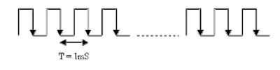
  • F=1/T
1 full-wave mean period 1mS, frequency: 1/1mS = 1000Hz or 1khz

READMORE...

Friday, December 25, 2009

Fungsi Dan Karakteristik Photodioda BPW41N

Fungsi Dan Karakteristik Photodioda

Photodioda often used as a catcher of light waves emitted by the Infrared. The amount of voltage or electrical current generated by the size depends photodioda radiation emitted by the infrared.

Photodiodes made from semiconductors with a popular material is silicon or gallium arsenide, and others include InSb, Carbuncle, PbSe. This Photodioda (BPW41N) can detect infrared light with wavelengths ranging from 800 to 1100 nm with a peak sensitivity at 950 nm wavelength as shown in the picture below

 Photodioda BPW41N Photodioda BPW41N
Kurva karakteristik photodioda BPW41NKurva karakteristik photodioda BPW41N

When a photon (a unit of light energy) from the light source is absorbed, it is generating an electron and produces a single pair of charge carriers, an electron and a hole where a hole is part of the semiconductor lattice is losing electrons. The direction of current through a semiconductor is opposite to the motion of charge carriers. I was in a Photodiode used to collect photons - causing charge carriers (such as current or voltage) flows / formed in the electrode parts.


Rangkaian Penkondisi Sinyal dari Photodioda

This circuit is used as a current-to-voltage converter by a factor of 1000 times (set by R3) due to backflow photodioda range from 1 to 100 UA the output of U1A is ranged from -1 to -100 mV. Negative voltage is then amplified again by the inverting amplifier circuit to the value corresponding to the input level of need, amount of reinforcement is done by adjusting the value potensimeter R1.

READMORE...

Gelang Warna (Nilai) Resistor

Gelang Warna (Nilai) Resistor

Resistor is the basic electronic components used to limit the amount of current flowing in one circuit. As the name implies is a resistive resistor and generally made of carbon materials. From Ohms law is known, the resistance is inversely proportional to the amount of current flowing through it. Unit resistance of a resistor is called Ohm or represented by the symbol W (Omega).

A common type of resistor is shaped tube with two feet of copper on the left and right. In the body there is formed a circle bracelet color code to identify the user greater ease without measuring the amount of resistance with ohmmeter. Color code is the manufacturing standards issued by EIA (Electronic Industries Association). as shown in the table below.


Table Gelang Warna Resistor


Example:
The order of the color ring (4 rings resistor color (4 gelang warna)): red, Purple, blue, gold
  • bracelet color 1: the first number
  • bracelet color 2: the second number
  • bracelet color 3: the multiplication factor
  • bracelet color 4: tolerance
The order of the color rings (5 rings resistor color (5 gelang warna)): brown, red, black, orange, brown
  • bracelet color 1: the first number
  • bracelet color 2: the second number
  • bracelet color 3: the third number
  • bracelet color 4: the multiplication factor
  • bracelet color 5: tolerance
The amount depends on the size watt resistor or the maximum power that can hold by resistors. Generally in the market available sizes 1 / 8, 1 / 4, 1, 2, 5, 10 and 20 watts. Resistor has a maximum power of 5, 10 and 20 watts is generally shaped white blocks and the value Direct printed dibadannya resistance, such as 1K 5W.

READMORE...

Rumus Mengitung Nilai Resistor Seri|Paralel

Resistor

Basically, all materials have resistive properties but some materials such as copper, silver, gold and metal materials generally have very little resistance. These materials deliver the electrical current very well, so-called conductors. The opposite of a conductive material, materials such as rubber, glass, carbon has a greater resistance restrain the flow of electrons and are called insulators.

Resistor is the basic electronic components used to limit the amount of current flowing in one circuit. As the name implies is a resistive resistor and generally made of carbon materials. From Ohms law is known, the resistance is inversely proportional to the amount of current flowing through it. Unit resistance of a resistor is called Ohm or represented by the symbol W (Omega).


Resistor physical

Other specifications that need to be considered in choosing a design resitor the resistance is greater than big watts his. Because resistors working with electrified, there will be a power dissipation of heat for W = I2R watts. The greater the physical size of a resistor can demonstrate the greater ability of the resistor power dissipation.

Generally in the market available sizes 1 / 8, 1 / 4, 1, 2, 5, 10 and 20 watts. Resistor which has a power dissipation of 5, 10 and 20 watts generally cubic-shaped elongated white square, but there is also a cylindrical. But usually for this jumbo-sized resistor resistance value printed directly on the body, for example 100W5W.


Rumus mengitung nilai resistor seri|paralel

Resistor paralel
Series of resistors in parallel will result in a replacement value of the smaller resistance. Below is an example of resistors that are arranged in parallel.

In parallel resistor circuit applies the formula:


Resistor seri
Series of resistors in series will result in the total resistance value is growing. In Below are examples of resistors arranged in series.

Series resistor in the circuit applies the formula:

READMORE...

Rangkaian Power Supplay

Electronic devices should be powered by direct current supply DC (direct current) which is stable in order to work properly. The battery or batteries is a source of DC power supply is best. But for applications that require greater power supply, the source of the battery is not enough. Sources of power supply is a source of alternating AC (alternating current) from power plants. This requires a power supply device that can change the AC into DC current.

Rangkaian Power Supplay

Now it should not need another effort to make good pwer supplay you do not need to look for op-amps, transistors and other components, because these circuits are packaged into a single fixed voltage regulator IC. Are now widely recognized as a component of 78XX series fixed positive voltage regulator and the 79XX series is a voltage regulator to remain negative. Even these components are usually already equipped with current limiting (current limiter) and also limiting the temperature (thermal shutdown). This component is only three pins, and by adding some components alone can be a series of power supply regulation was good.

rangkaian power supplaySkema rangkaian power supplay

It's just to note that the IC regulator circuit that can work, the input voltage must be greater than the output voltage regulator. Usually the difference voltage Vin to the recommended VM is in the component datasheet. Usage heatshink (Aluminum cooling) is recommended if these components are used to supply large currents. In the datasheet, these components can pass the maximum current reached 1 A.

READMORE...

Tuesday, December 22, 2009

1.25V-15.19V Regulator/Adaptor Variabel Digital

Rangkaian Regulator/Adaptor Variabel Digital

This is a series regulator with variable output from the digital 1.25V to 15.19V The first section of the circuit comprises a digital up-down counter built around IC1, a quad 2-input NAND Schmitt trigger (IC CD4093), followed by IC2, a binary up-down counter (CD4029 IC). Two gates of IC CD4093 are used to generate the up-down logic using the push buttons S1 and S2, respectively, while the other two gates form an oscillator to provide clock pulses to IC2 (CD4029). The frequency of oscillations can be varied by changing the value of capacitor C1 or preset VR1. IC2 receives clock pulses from the oscillator and produces a binary sequential output. As long as its pin 5 is low, the counter continues to count at the rising edge of each clock pulse, but stops counting as soon as its pin 5 is brought to logic 1. Logic 1 at pin 10 makes the counter to count upwards, while logic 0 makes it count downwards. Therefore the counter counts up by closing switch S1 and counts down by closing switch S2. The output of counter IC2 is used to realize a Digitally variable resistor. This section consists of four N / O reed Relays that need just about 5mA current for their operation. (The original circuit containing quad bilateral switch IC 4066 has been replaced by reed Relays switches operated by transistorised because of unreliable operation of the former.)

Rangkaian Variabel   Regulator (Adaptor) Digital Skema rangkaian regulator/adaptor variabel digital

The switching action is performed using BC548 transistors. External resistors are connected in parallel with the reed relay contacts. Particular if the relay contacts are opened by the control input at the base of a transistor, the correspond-ing resistor across the relay contacts gets connected to the circuit. The table shows the theoretical output for various combinations of digital inputs. The measured output is nearly equal to the theoretically calculated IC3 outputs across the regulator (LM317).

output of this regulator minimum (1.25V). As count-up switch S1 is pressed, the binary count of IC2 increases and the output starts increasing too. At the highest count output of 1111, the output voltage is 15.19V (assuming the in-circuit resistance of the preset VR2 as zero). Preset VR2 can be used for trimming the output voltage as desired. To decrease the output voltage within the range of 1.25V to 15.2V, count-down switch S2 is to be depressed.

READMORE...
 
Skema Rangkaian Elektronika