Wednesday, May 26, 2010

Rangkaian Infra Red Remote Tester

Infra Red Remote Tester

The circuit is very effective to test the remote controls what still works or not, the remote record will be tested using infra red. Examples of the TV remote, AC and others. Please try I am sure 100% will be successful.

Rangkaian Remote TesterRangkaian Remote Tester

The workings of the circuit is very simple, when the infra red sensor receive infrared signals pin 2 sensor will produce a voltage, this voltage will drives the PNP transistor so that the LED lamp and piezo disc (BZ) is active. for the power supply you can use a 9 volt battery and then use IC 7805 or use 1.5 volt batteries x 3

Following the specification of components installed
  • Transistor BC557
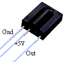
  • TSOP 1738 Sensor Infra Red
  • R1 = 10k ohm ¼ watt Resistor
  • R2 = 1k ohm ¼ watt Resistor
  • R3 = 1k ohm ¼ watt Resistor
  • BZ = piezo disc
  • led
TSOP 1738 Sensor Infra Red


Features
  • Photodetector and preamplifier circuit in the same casing.
  • Receives and amplifies the infrared signal without any external component.
  • 5 V output (active at level 0).
  • 38 kHz integrated oscillator.
  • High sensitivity.
  • High level of immunity to ambient light.
  • Improved shielding against electrical field interference.
  • TTL and CMOS compatibility.
  • Applications: infrared remote control.
Technical specification
  • Supply: 5 V
  • Power consumption: 0.4 to 1.0 mA
  • Min. Ee irradiation: 0.35 mW/m2 typ.
  • Angle of detection: 90
  • Dimensions of the casing (mm): 12.5 x 10 x Thickness 5.8
  • Temperature range: -25 C to +85 C

READMORE...

Sunday, May 23, 2010

Rangkaian Pengukur Jarak

This circuit Can be Used to Measure distance covered by bicycle using a reed switch as the sensor and use the magnet tied to a wheel. Detection of rolling is then made by a proximity effect, Pls the magnet close to the reed switch. This close / open reed switch contact Can use to make on-off signal. 68HC908QY4 microcontroller function for counting the pulse signal Produced by reed switches, and then Direct display in meter unit through lcd 16 x 1 line LCD

 Pengukur Jarak Prototipe Pengukur Jarak Prototipe

Rangkaian Pengukur JarakSkema rangkaian pengukur jarak

To Interface signals for LCD are D4-D7, RS and E. 4-bit It was interfacing, no busy checking. D0-D3 and R / W # is not Used, so We must tie to GND. Since We Can not check Busy bit, so the delay routine must be ready LCD Used to wait for command and writing data. The sensor inputs are PTA2 for reed switch contact and PTA0 for 0 / +5 V analog input can use a small phone jack for both sensors. in the image below shows a sample sensor and cable making. Later shrinkage tube We need to protect the sensor. The position sensor Pls Pls fix to the bicycle wheel Also Important. We need the magnetic flux perpendicular to the contact.

sensor and cable making

Software/program

Software for write to68HC908QY4 microcontroller is s-record.hex ,which was written by C-language ,the source code is firmware source code.

source http://chaokhun.kmitl.ac.th

READMORE...

Wednesday, May 19, 2010

Rangkaian Line Follower ROBOT Berbasis AT89C2051

This Circuit of Line Follower ROBOT has been getting from VingPeaw Competition Award winner in 2543, the robot built with mikrokontroler AT89C2051, L293D, and four IR sensors. Simple circuit and platform, quick tracking and easy-understand program using C language.

The Line Follower ROBOT designed which use two motors control rear wheels and the single front wheel is free. It has 4-infrared sensors on the bottom for detect black tracking tape, when the sensors detected black color, output of comparator, LM324 is low logic and the other the output is high.

Prototipe Line Follower ROBOT

Rangkaian Line Follower ROBOT
Microcontroller AT89C2051 and H-Bridge driver L293D were used to control direction and speed of motor.
Position of sensors the robot, left hand side is side view and right hand side is top view
Skema rangkaian Infrared sensors and comparators

Software/program

Software for write to AT89C2051 is robot1.hex ,which was written by C-language ,the source code is robot1.c compiled by using MC51 in TINY model with my start up code robot.asm .

Source: http://www.kmitl.ac.th

READMORE...

Tuesday, May 18, 2010

Rangakaian Downloader Mikrokontroler AVR Menggunakan USB

This circuit is a downloader for Atmel AVR microcontroller. The circuit uses ATMega48 or ATmega8 and a few other passive components. Programmer or a downloader uses a USB-only drive firmware (firmware-only USB driver), does not require a special USB controller.

Rangakaian Downloader Mikrokontroler AVR Menggunakan USBSkema Rangakaian Downloader
Mikrokontroler AVR Menggunakan USB


Features
  • Can be used for a variety of platforms, have been tested for Linux, Mac OS and Windows;
  • Does not require special controllers or smd components;
  • Speeds may reach 5kByte/detik programming;
  • Option SCK to support low-speed microcontroller targets < 1.5 Mhz
Software
  • AVRDUDE USBasp support since version 5.2 - Take AVRDUDE.
  • Khazama AVR - Programmer is an application Windows XP / Vista for USBasp and avrdude.
  • EXtreme Burner - AVR is a Windows GUI software specifically for USB AVR programmer USBasp based, not use AVRDude.

Source

READMORE...

Sunday, May 16, 2010

Rangkaian Thermometer Berbasis Mikrokontroler AT89S52

This is a circuit of a microcontroller AT89S52 Thermometer and 12-bit ADC LTC1298, programs written in the language c program with digital filtering and interface the LED display. The reading provides 0.1C sensitivity.

The hardware block and circuit diagram is shown in Fig below. The sensor is epoxy molded thermistor. The circuit for signal conditioning is a simple voltage divider. The ADC is 12-bit SPI interface LTC1298 analog-to-digital converter. The microcontroller is Atmel 89S52. The display has four digits 0.5 inches 7-segment LED. The segment driver provides 32-bit CMOS output.

Rangkaian Thermometer Berbasis Mikrokontroler AT89S52
Skema Rangkaian Thermometer Berbasis Mikrokontroler AT89S52

Rangkaian Thermometer Berbasis Mikrokontroler AT89S52
Thermometer Block Diagram

The ADC is 12-bit (LTC1298 or MC3202) are two channels, CH0 and CH1. The input signal from thermistor for ADC channel 0 is simple voltage divider. Channel1 is available for other sensor. The sample shown in schematic is HIH-3160 Honeywell Relative Humidity Sensor. The ADC chip is interfaced with MCU, 89S52 with P1.1, P1.2 and P1.3. The display has 4-digit LED. The 4094 CMOS shift register drives the LED directly.


Software

The main function is time triggered by 10ms timer0 running. The ADC is updated on LED every 10 ticks.

while(1)
{
while(!cputick)
continue;
cputick=0;
print_ADC();
}

The function that reads 12-bit data from ADC is read_ADC(char n). The function has two loops. First loop is to send 4-bit command. And the second loop is 12-bit to shift the data from ADC.

sbit Data = P1^1;
sbit CLK = P1^2;
sbit CS = P1^3;


int read_ADC(char n)
{ int k;
char i,channel;
k=0;
CS=0;
if(n==0) channel=0x0d;
else channel=0x0f;

for(i=0;i<4;i++) clk =" 0;" data =" 1;" data =" 0;" clk =" 1;" data =" 1;" clk =" 0;" i="0;i<12;i++)" clk="1;" clk="0;" cs =" 1;">

To provide smooth reading, I added the 5-point moving average to the raw data. The function low_pass_filte1( ) is used to filter the high frequency noise. The reading is calibrated to degree Celsius with Platinum 100 standard thermometer. We found the equation y=0.0323x-15.122.

int low_pass_filter1(void)
{
x5=x4;
x4=x3;
x3=x2;
x2=x1;
x1=read_ADC(0);
return(x1+x2+x3+x4+x5)/5;
}

float read_temp1_filter(void)
{
return(0.0323*low_pass_filter1()-15.122);
}


READMORE...

Thursday, May 13, 2010

Rangkaian Control DC Fan Menggunakan Remote TV

Control DC Fan Menggunakan Remote TV

This circuit measures temperature in Celsius and displays it on an alphanumeric LCD. When temperature rise to 40C an alarm is activated and the electromechanical relay is also activated which drives a fan to keep the temperature at a level. Another feature of this circuit is that you can use the keys "1,2,3,4" of a Philips TV IR remote to turn on or off three relays. Key '4' is used to turn on or off the buzzer alarm.

Rangkaian Control DC Fan Menggunakan Remote TVSkema Rangkaian Control DC Fan Menggunakan Remote TV


The MCU is the ATMEL AT89C51. The LM35 is an TO-92 package temperature sensor. It senses heat from 0C to 100C. The output provides 10mV/C. We use the simple analog to digital converter, ADC0804 to convert the analog signal to digital data. The 8-bit digital data is tied to PORT1. This data is processed by microcontroller and the temperature is displayed on lcd connected to PORT2. The control pins of lcd are connected to PORT0. Some bits of the PORT0 also control the relays and buzzer. The ULN2003 chip is used to drive the relays. Pin 1 to 7 are the inputs and 10 to 16 are respective outputs. Pin 8 is ground and pin 9 is connected to the output of 7808 voltage regulator. The 7805 voltage regulator drives rest of the circuit. I used a standard buzzer driven by LM555 timer/oscillator chip. The 555 circuit is a multivibrator having output for driving the buzzer. We may use any IR receiver module and connect the output to pin 10 of microcontroller. The relay connected to pin 13 of ULN2003 turns on when temperature rises above 40C.

You may download all files in zip format. The file contains the images of completed project, hex file, circuit diagram and pcb file.

Source

READMORE...
 
Skema Rangkaian Elektronika