Monday, September 27, 2010

Rangkaian Radar Pompa Air (Kontrol Ketinggian Air)

Radar Pompa Air (Kontrol Ketinggian Air)

By means of a Relay, employed to drive a water pump, this circuit provides automatic level control of a water reservoir or well.
Skema Rangkaian Radar Pompa air


Note:
  • The two steel rods must be supported by a small insulated (wooden or plastic) board.
  • The circuit can be used also with non-metal tanks, provided a third steel rod having about the same height of the tank will be added and connected to the circuit's negative ground.
The shorter steel rod is the "water high" sensor, whereas the longer is the "water low" sensor. When the water level is below both sensors, IC1C output (pin #10) is low; if the water becomes in contact with the longer sensor the output remains low until the shorter sensor is reached. At this point IC1C output goes high, Q1 conducts, the Relay is energized and the pump starts operating.

Now, the water level begins to decrease and the shorter sensor will be no longer in contact with the water, but IC1C output will be hold high by the signal return to pin #5 of IC1B, so the pump will continue its operation. But when the water level falls below the longer sensor, IC1C output goes low and the pump will stop.

SW1 is optional and was added to provide reverse operation. Switching SW1 in order to connect R3 to pin #11 of IC1D, the pump will operate when the reservoir is nearly empty and will stop when the reservoir is full. In this case, the pump will be used to fill the reservoir and not to empty it as in the default operating mode.

List Component
  • R1,R2: 15K 1/4W Resistors
  • R3: 10K 1/4W Resistor
  • R4: 1K 1/4W Resistor
  • D1: LED
  • D2: 1N4148 Diode
  • IC1: 4001
  • Q1: BC337 NPN Transistor
  • SW1: witch
  • RL1: Relay with SPDT 2A @ 230V switch, Coil Voltage 12V
READMORE...

Wednesday, September 01, 2010

Rangkaian ON OFF Sleep Timer Switch

ON/OFF Sleep Timer Switch

This timer was designed mainly to switch off a portable radio after some time: in this way, one can fall asleep on the sand or on a hammock, resting assured that the receiver will switch off automatically after some time, saving battery costs.

Rangkaian ON OFF Sleep Timer SwitchSkema Rangkaian ON OFF Sleep Timer Switch

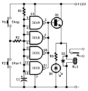
R1 and C1 provide a very long time constant. When P2 is momentarily closed, C1 discharges and the near zero voltage at its positive lead is applied to the high impedance inputs of the four gates of IC1 wired in parallel. The four paralleled gate outputs of the IC go therefore to the high state and the battery voltage is available at Q1 Emitter. When P2 is released, C1 starts charging slowly through R1 and when the voltage at its positive lead has reached about half the battery voltage, the IC gate outputs fall to zero, stopping Q1. This transistor can directly drive a portable radio receiver or different devices drawing a current up to about 250mA. Connecting a Relay across the Emitter of Q1 and negative ground, devices requiring much higher voltage and current operation can be driven through its contacts.

Pushing on P2 for 1 to 5 seconds, the circuit starts and then will switch off after about 35 minutes. This time delay can be varied by changing R1 and/or C1 values. P1 will stop the timer if required. LED D1 is optional and can be useful to signal relay operation when the load is placed far from the timer.

List Component
  • R1: 10M 1/4W Resistor
  • R2: 4K7 1/4W Resistor
  • R3: 1K 1/4W Resistor
  • C1: 220µF/ 25V Electrolytic capacitor
  • D1: LED
  • D2: 1N4148
  • IC1: 4011 Quad 2 Input NAND Gate CMos IC
  • Q1: BC337
  • P1,P2: SPST Pushbuttons
  • RL1: 12V Relay
Source

READMORE...

Tuesday, August 31, 2010

Skema Dancing LEDs, Following the Rhythm of Music

Dancing LEDs

The basic circuit illuminates up to ten LEDs in sequence, following the rhythm of music or speech picked-up by a small microphone. The expanded version can drive up to ten strips, formed by up to five LEDs each, at 9V supply.

Rangkaian Dancing LEDsSkema Rangkaian Dancing LEDs

IC1A amplifies about 100 times the audio signal picked-up by the microphone and drives IC1B acting as peak-voltage detector. Its output peaks are synchronous with the peaks of the input signal and clock IC2, a ring decade counter capable of driving up to ten LEDs in sequence.
An additional circuit allows the driving of up to ten strips, made up by five LEDs each (max.), at 9V supply. It is formed by a 10mA constant current source (Q1 & Q2) common to all LED strips and by a switching transistor (Q3), driving a strip obtained from 2 to 5 series-connected LEDs. Therefore one transistor and its Base resistor are required to drive each of the strips used.

List Component of Dancing LEDs Circuit
  • R1: 10K 1/4W Resistor
  • R2,R3: 47K 1/4W Resistors
  • R4: 1K 1/4W Resistor
  • R5,R6,R7: 100K 1/4W Resistors
  • R8: 820R 1/4W Resistor
  • C1,C3: 100nF/63V Ceramic or Polyester Capacitors
  • C2: 10µF/50V Electrolytic Capacitor
  • C4: 330nF/63V Polyester Capacitor
  • C5: 100µF/25V Electrolytic Capacitor
  • D1: 1N4148
  • D2-D11: LEDs (any type and color)
  • IC1: LM358
  • IC2: 4017
  • M1: electret microphone
  • SW1: SPST Switch
  • B1: 9V PP3 Battery
Additional circuit parts:
  • R9,R10: 10K 1/4W Resistors
  • R11: 56R 1/4W Resistor
  • D12,D13 etc.: LEDs (any type and color)
  • Q1,Q2: BC327
  • Q3: BC337
Note:
  • The sensitivity of the circuit can be varied changing R4 value.
  • C4 value can be varied from 220 to 470nF in order to change the circuit speed-response to music peaks.
  • Adopting the additional circuit, only one item for R10, R11, Q1 and Q2 is required to drive up to ten LED strips. On the contrary, one item of R9 and Q3 is necessary to drive each of the strips you decided to use.
  • Each R9 input must be connected to IC2 output pins, in place of the LEDs D2-D11 shown. R8 must also be omitted.
  • Whishing to use a lower number of LEDs or LED strips, pin #15 of IC2 must be disconnected from ground and connected to the first unused output pin.
  • For example: if you decided to use 5 LEDs, pin #15 of IC2 must be connected to pin #1; if you decided to use 8 LEDs, pin #15 of IC2 must be connected to pin #9 etc.
  • Current drawing of the circuit is about 10mA.
  • Whishing to use a wall-plug adapter instead of a 9V battery, you can supply the circuit at 12V, allowing the use of up to 6 LEDs per strip, or at 15V, allowing the use of up to 7 LEDs per strip.
Source

READMORE...

Monday, August 23, 2010

Rangkaian LED 220VAC Sebagai Lampu Penerangan

The LED has advantages over other lighting technology. LED supposedly can hold up to 100,000 hours. This means that if the LED light 24 hours a day he would hold for 10 years. Whereas Fluorencent lights are usually only able to survive 1-3 years.

This is a modified version of the circuit, Super bright LED Night Light published that can directly connect to the netting PLN (220VAC).

rangkaian LED 220VACSkema rangkaian LED 220VAC

rangkaian LED 220VAC
Note:
Dangerous...!! this circuit directly connected to the netting of electricity, voltage 220V electricity it could sting you. Avoid working in damp and directly with ground

This is the circuit of a well tried and reliable 230-volt AC mains operated 24 LEDs (super bright LEDs 50mA). While Practically compare the brightness Between this and 11watts tube circuit, the LED light is much better. The layout is made in such a way, you get uniform Illumination. A photographs of the cicuit is Also given in this post.

READMORE...

Friday, August 20, 2010

Rangkaian Speaker Protector sederhana

Speaker Protector sederhana

This circuit follows will connects the speakers to the power amplifier output only a few seconds after the amplifier is powered ON, so that the speakers do not accept popped up by a high voltage and you would not Hear a loud thud sound from the speakers When the amplifier is switched on. This stuff is very harmful to the speakers.

Rangkaian Speaker Protector sederhanaSkema rangkaian speaker protector

When the amplifier is powered on the bridge D1 also gets powered through the amplifier’s power switch. Capacitor C1 filters the output of bridge rectifier D1. When the power switch is made ON, the transistor Q1 gets switched ON only after the capacitor C2 is sufficiently charged (0.7V) through the resistor R1. Here the value of C2 and R1 are so selected that the time delay is around 2 seconds. So the relay gets activated only after a few seconds the amplifier is powered ON and until that time the speaker will be kept isolated from the amplifier’s audio output as the speaker is connected to the amplifier’s output through the N/O contact of the relay. During this initial delay period the output of amplifier will be grounded by the resistor R2 through the N/C contact of the relay. This is done in order to ensure that the DC blocking capacitor at the amplifier’s output is charged before it is connected to the speaker.

Rangkaian Speaker Protector sederhanaBetter quality speaker protector Circuit

READMORE...

Sunday, August 15, 2010

Rangkaian Magnetic proximity sensors

Here is the circuit diagram of a magnetic proximity switch sensor which can be used in various applications. The circuit is based on a magnetic reed switch as the proximity sensor. A monostable multivibrator based on NE555 and a toggle flip flop CD4013 does the rest of the circuit.

rangkaian magnetic proximity sensors  Skema rangkaian magnetic proximity sensors
magnetic reed switch magnetic reed switch sensor

The magnetic proximity switch sensor circuit, in principle, consists of a reed switch at its heart. When a magnet is brought in the vicinity of the reed switch it operates and controls the rest of the switching circuit. In place of the reed switch, one may, as well, use a general-purpose electromagnetic reed relay as the sensor, if required. These tiny reed relays are easily available as they are widely used in telecom products. The reed switch or relay to be used with this circuit should be the normally open type.

When a magnet is brought in the vicinity of the sensor element for a moment, the contacts of the reed switch close to trigger timer IC1 wired in monostable mode. As a consequence its output at pin 3 goes high for a short duration and supplies clock to the clock input (pin 3 CD4013). LED D2 is used as a response indicator.

This CMOS IC2 consists of two independent flip-flops though here only one is used. Note that the flip-flop is wired in toggle mode with data input (pin 5) connected to the Q (pin 2) output. On receipt of clock pulse, the Q output changes from low to high state and due to this the relay driver transistor T1 gets forward-biased. As a result the relay RL1 is energised.

READMORE...
 
Skema Rangkaian Elektronika