Showing posts with label Inverter/Ups. Show all posts

Tuesday, June 07, 2011

500 Watt Inverter 12VDC to 220VAC

The circuit of 500 Watt Inverter 12VDC to 220VAC is made using a transistor. central component of this inverter circuit is a configuration of 2 pieces of transistors Q1 and Q2 which form a circuit of Flip-Flop. The output of the flip-flop Q1 and Q2 then in severance for each pulse to complement each other using a compiled circuit by Q3 and Q4. Output which complement each other is then given to the driver transistors Q5 and Q6 form the transistor 2SC1061. Power Inverters of this circuit is composed using parallel transistors Q7, Q8 and Q7x, Q8x a form of 2N3055 power transistor 10 pieces. schematic a complete of Inverter 500 Watt circuit can be seen as follows.
Rangkaian 500 Watt Inverter 12VDC to 220VACSkema Rangkaian 500 Watt Inverter
12VDC to 220VAC

Step up part of this inverter circuit using a transformer 12VCT/500VA in secondary and primary 0 - 220V. While the frequency is determined by the flip-flop which is set to 50 Hz.

Note:
  • Q7, Q8 and Q7x, Q8x require heat sink.
  • Output power of this dc dc converter is around 500 watts.
  • An optional 40A fuse can be added in circuit to the 12V supply line.
  • T1 can be a 12-CT-12V /250V/40A mains transformer.

READMORE...

12VDC – 220VAC Inverter Using Cmos CD4047

This inverter circuit will convert 12V DC power from battery to 22oV AC as home power replacement. The inverter can be used for small electronic appliances such as lamp, radio, phone charger, disk player etc.
12VDC – 220VAC inverter circuitSkema Rangkaian 12VDC – 220VAC Inverter
Using Cmos CD4047

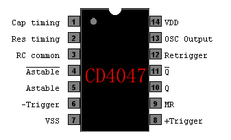
CD4047 Pinout

The inverter circuit has a central component, the CMOS 4047, and converts a 12V DC voltage to 220V AC voltage. 4047 is utilised as a astable multivibrator. At pin 10 and 11 we find a rectangular symmetrically signal which is amplified by tow Darlington transistors T1 and T2 and finally reaches the secondary coil of a transformer network (2 x 10V/100VA). Primary coil terminals voltage is 220 alternative voltage. To obtain a better performance use a toroidal core transformer with reduced losses. With P1 the output frequency can be regulated between certain limits (50…400Hz).


This Circuit From: http://apowersupply.com

READMORE...

Wednesday, March 23, 2011

100Watt Inverter Circuit by IRF44 Mosfet

This inverter circuit will provide a very stable 230V Output Voltage. Frequency of operation is determined by a VR1 and is normally set to 60 Hz. Various “off the shelf” transformers can be used. Or Custom wind your own for best results. Additional MosFets can be paralleled for higher power. It is recommended to Have a “Fuse” in the Power Line and to always have a “Load connected”, while power is being applied. The Fuse should be10 Amps per 100 watts of output. The Power leads must be heavy enough wire to handle this High Current Draw

100Watt Inverter Circuit by IRF44 MosfetSkema Rangkaian 100Watt Inverter by IRF44 Mosfet

IRF44 PINNING

Absolute Maximum Ratings of IRF44 Mosfet
  • Continuous Drain Current (25°C, 10V) = 49 A
  • Continuous Drain Current ( 100°C, 10V) = 35 A
  • Pulsed Drain Current = 160 A
  • Power Dissipation = 94 W
  • Gate-to-Source Voltage = ± 20 V
  • Avalanche Current = 25 A
  • Operating Junction = -55 to + 175

READMORE...

Monday, March 07, 2011

12VDC to 220VAC Inverter Circuit Using IC 555

This is a simple 12VDC to 220AC inverter circuit that can be used produces an AC output at line frequency and 220AC or different voltage by selecting transformer T1. The 555 IC is configured as a low-frequency oscillator, tunable over the frequency range of 50 to 60 Hz by Frequency potentiometer R4.

12VDC to 220VAC Inverter Circuit 12VDC to 220VAC Inverter Circuit

The 555 feeds its output (amplified by Q1 and Q2) to the input of transformer T1, a reverse-connected filament transformer with the necessary step-up turns ratio. Capacitor C4 and coil L1 filter the input to T1, assuring that it is effectively a sine wave. Adjust the value of T1 to your voltage. The output ( in watts) is up to you by selecting different components.

Input voltage is anywhere from +5V to +15Volt DC, adjust the 2700uF cap's working voltage accordingly. Replacement types for Q1 are: TIP41B, TIP41C, NTE196, ECG196, etc. Replacement types for Q2 are: TIP42B, TIP42C, NTE197, ECG197, etc.

READMORE...

Thursday, October 28, 2010

Rangkaian 12VDC Fluorescent Lamp Driver

Whenever there is a need for battery-powered lighting, like for camping, solar powered cottages, cars, boats, planes, or emergency purposes, fluorescent lamps have a great appeal. Firstly, they are very much more efficient than glow lamps, so they produce much more light for less power consumption. Secondly, their light color stays constant while the battery runs down.

In this article I will offer driver circuit for 12 V/5Watt fluorescent lamp, this circuit used a normal 220 to 10V stepdown transformer in reverse to step 12V to about 240V to drive a lamp without the need to warm the filaments.
Rangkaian 12VDC Fluorescent Lamp DriverSkema Rangkaian 12VDC Fluorescent Lamp Driver

Note:
  • Q1 (IRF510 MOSFET) must be installed on a heat sink
  • Dangerous ...!! Please be careful, This series contains 220 VAC that can sting you.

The IC1 TLC 555 is wired as an astable multivibrator for producing the necessary oscillations.The MOSFET Q1 is used to amplify the oscillations produced by the IC1.The out put of MOSFET is connected to the primary of the step up transformer to produce a ~240 V AC for driving the florescent lamp.

List Component:
  • C1 100uf /25V Electrolytic Capacitor
  • C2,C3 100nf Ceramic Capacitor
  • C4 100nf /1KV Ceramic Capacitor
  • R1 1K Resistor
  • R2 2.7K Resistor
  • Q1 IRF510 MOSFET
  • U1 TLC555 Timer IC
  • T1 300mA, 10V/220v Transformer
  • LAMP 5W Fluorescent Lamp
  • MISC Board, Wire, Heatsink For Q1

READMORE...

Sunday, December 20, 2009

Rangkaian Neon Emergency Light Battery 6 volt

Neon Emergency Light Battery 6 volt


This circuit is IC controlled emergency light. This series of automatic switching-on of the light on mains failure and battery charger with overcharge protection. When mains is absent, the relay RL2 is in deenergised state, feeding battery supply to the inverter section via its N / C contacts and switch S1.

rangkaian neon emergency light battery 6 volt
Skema rangkaian neon emergency light battery 6 volt


The inverte
r section comprises IC2 (NE555) which is used in a stable fashion to produce sharp pulses at the rate of 50 Hz for driving the MOSFETs. The output of IC3 is fed to the gate of MOSFET (T4) directly while it is applied to MOSFET (T3) after inversion by gate transistor T2. Thus the power amplifier built around MOSFETs T3 and T4 functions in push-pull mode. The output across the secondary of transformer X2 can easily drive a 230-volt, 20-watt fluorescent tube. In case light is not required to be on during mains failure, simply flip the switch S1 to off position. Battery overcharge preventer circuit is built around IC1 (LM308). Its non-inverting pin is held at a reference voltage of approximately 6.9 volts which is obtained using diode D5 (1N4148) and 6.2-volt zener D6.

The inverting pin of IC1 is connected to the positive terminal of battery. Thus when mains supply is present, Comparator IC1 output is high, unless battery voltage exceeds 6.9 volts. So the transistor T1 is normally forward biased, which energises relay RL1. In this state the battery remains on charge via the N / O contacts of relays RL1 and current limiting resistor R2. When battery voltage exceeds 6.9 volts (overcharged condition), IC1 output goes low and gets deenergised relay RL1, and thus stops further charging of battery. MOSFETs T3 and T4 may be mounted on suitable heat sinks.

READMORE...

Wednesday, December 16, 2009

Converter 12 to 24VDC

Converter 12 to 24VDC

This is DC to DC converter can provide up to 24V from a 12V volt DC. It can be used to run radios, small lights, relays, horns and other 24V accessories from a 12V vehicle with a maximum draw of about 800mA. It can be used to charge one 12V battery from another, or step up the voltage just enough to provide necessary overhead for a 12V linear regulator.

rangkaian converter 12 to 24 VDC Skema rangkaian converter 12 to 24 VDC

IC LM358 Op-amp Pinning


Op-amp as a squarewave oscillator to ring an inductor and another op-amp in a feedback loop, it won't drift around under varying loads, providing a stable 24V source for many applications. With a wide adjustment in output this circuit has many uses.

Note:
  • R6 sets the output voltage. This can be calculated by Vout = 12 x (R8/(R8+R7)) x (R6B/R6A).
  • L1 is made by winding 60 turns of 0.63MM magnet wire on a toroidial core measuring 15MM (OD) by 8MM (ID) by 6MM (H).
  • D2 can be any fast recovery diode rated at greater then 100V at 5A. It is very important that the diode be fast recovery and not a standard rectifier.
  • Transistor Q1 will need a heatsink.

List component

R1, R2, R3, R4, R8, R7 6 100K_____1/4W Resistor
R5_______________________470 Ohm 1/2W Resistor
R6_______________________10K Linear Pot
C1_______________________0.01uF Mylar Capacitor
C2_______________________0.1uF Ceramic Disc Capacitor
C3_______________________470uF 63V Electrolytic Capacitor
D1_______________________1N4004 Rectifier Diode
D2_______________________BY229-400 Fast Recovery Diode
Q1_______________________BC337 NPN Power Transistor
U1_______________________LM358 Dual Op Amp IC
L1_______________________ See Notes

READMORE...

Friday, September 11, 2009

Rangkaian 100watt Inverter 2N3055

This is a 100 Watt inverter circuit using minimum number of components. Here circuit used IC CD 4047 IC from Texas Instruments for generating the 100 Hz pulses and four 2N3055 transistors for driving the load.

IC1 Cd4047 wired as an astable multivibrator produces two 180 degree out of phase 100 Hz pulse trains. These pulse trains are are preamplifes by the two TIP122 transistors. The out puts of the TIP 122 transistors are amplified by four 2N 3055 transistors (two transistors for each half cycle) to drive the inverter transformer. The 220V AC will be available at the secondary of the transformer.Nothing complex just the elementary inverter principle and the circuit works great for small loads like a few bulbs or fans.If you need just a low cost inverter in the region of 100 W,then this is the best.

Inverter 100watt

Skema Rangkaian Inverter 100watt 2N3055


The maximum allowed output power of an inverter depends on two factors.The maximum current rating of the transformer primary and the current rating of the driving transistors, For example ,to get a 100 Watt output using 12 V car battery the primary current will be ~8A ,(100/12) because P=VxI.So the primary of transformer must be rated above 8A. Also here ,each final driver transistors must be rated above 4A. Here two will be conducting parallel in each half cycle, so I=8/2 = 4A .


Note:

  • A 12 V car battery can be used as the 12V source.
  • Use the POT R1 to set the output frequency to50Hz.
  • For the transformer get a 9-0-9 V , 10A step down transformer.But here the 9-0-9 V winding will be the primary and 220V winding will be the secondary.

IC CD4047 Description


IC CD4047


IC CD4047B is capable of operating in either the monostable or astable mode. It requires an external capacitor (between pins 1 and 3) and an external resistor (between pins 2 and
3) to determine the output pulse width in the monostable mode, and the output frequency in the astable mode. Astable operation is enabled by a high level on the astable input or low level on the astable input. The output frequency (at 50% duty cycle) at Q and Q outputs is determined by the
timing components. A frequency twice that of Q is available at the Oscillator Output; a 50% duty cycle is not guaranteed. Monostable operation is obtained when the device is triggered
by low-to-high transition at a trigger input or high-tolow transition at b trigger input. The device can be retriggered by applying a simultaneous low-to-high transition to both the a trigger and retrigger inputs. A high level on Reset input resets the outputs Q to low, Q to
high.

READMORE...

Friday, July 24, 2009

Rankaian Konverter 12volt - 5 volt Meggunakan Dioda Zener

Konverter 12 Volt to 5  volt
Skema Rangkaian Konverter 12 Volt ke 5 Volt

Converter is a series of functions to change the voltage 12 to be 5 Volt. the core of this series is the zener diode. due to a fall in voltage Zener diode 12 will be 5.7 volt. voltage in 5.7 volt electrical currents strengthened by taransiator Q1

To get a different output voltage you can change the zener diode as needed. for example, if you need a converter from 12 to 9 volt change zener Diode eat 5.7 to 10 volt

components List:
  • R1 = 560 ohm
  • C1 = 1000uF/40V
  • C2 = 10uF/25V
  • C3 = 330nF
  • Z1 = 5,7V
  • Q1 = ECG184, NTE184


READMORE...

Thursday, July 23, 2009

Rangkaian Lampu Neon (TL) 12 Volt

Rangkaian Lapu Neon (TL) 12 Volt function to set the lights Neon (TL) using voltage 12 Volt (12 volt batteray). This series is based 2N3055 transistor and some components that work as a series of oscilator Volet with feedback through the L1. Oscilator frequency of this work is influenced by the value of R, C and L

When the oscillation output from the collector, it will appear different on the high potential end of the L3. to make the shuttle can see in the image such as shown in Figure

Skema Rangkaian Lapu Neon (TL) 12 Volt
Skema Rangkain Lampu Neon (TL) 12 Volt

notes:
  • L1,L2 = 30 Lilit/0.8mm
  • L3 = 600 lilit/0.1mm
  • A point is represented polarity, while B is its opposite polarity.


READMORE...

Tuesday, June 16, 2009

Rangkaian UPS sedehana

Uninterruptible power supply (UPS), also known as a battery back-up, provides emergency power and, depending on the topology, line regulation as well to connected equipment by supplying power from a separate source when utility power is not available. It differs from an auxiliary or emergency power system or standby generator, which does not provide instant protection from a momentary power interruption. A UPS, however, can be used to provide uninterrupted power to equipment, typically for 5–15 minutes until an auxiliary power supply can be turned on, utility power restored, or equipment safely shut down.

While not limited to safeguarding any particular type of equipment, a UPS is typically used to protect computers, data centers, telecommunication equipment or other electrical equipment where an unexpected power disruption could cause injuries, fatalities, serious business disruption or data loss.

picture below is a simple series of UPS. This series UPS has a power of 60W (if the transformer is used more, the power output of the UPS is also greater).

UPS
Gambar Skema Rangkaian UPS

description :
Transformer: Min 4 ampere or more
Diode|Dioda: Min 5 ampere or more
Irfz 44: Paste cooling plate


When normal PLN Electricity, of the adapter (the series of the most left) will produce voltage 12 - 13 volt / 5 ampaere. This voltage is used to fill mengoprasikan UPS batery and therefore this UPS if you plan to load a higher modifikasilah of this series that have a higher ampere. PLN electricity when dead, the source voltage in the switch to akan bateray

When electricity PLN suppressed, the source voltage will switch to the battery. ups that may be living longer while the power off, use battery who have ampere / hour high (large) or can also install some of the ways in parallel battery

READMORE...

Sunday, May 24, 2009

CIRCUIT OF SIMPLE ON LINE UPS


physical irfz44 & CD4047 chip


Simple Circuit of UPS on line


UPS (Uninterruptible Power Supply), is used to anticipate the power off. Output series UPS has a power of 60W (if the transformer is used the greater the power will higher). Before the series there is a major series of the adapter has a voltage between 9V - 12V with strong currents of 5A. Voltage generated is used to operate the series and fill the battery. UPS is designed to keep electronic devices can run even if the electricity off.


READMORE...

Sunday, January 04, 2009

Rangkaian Inverter 12 - 220 Volt

Pengertian Inverter


Inverter is a series of functions to change the dc voltage into ac voltage.
One of the purposes inverter that is popular enough to raise the dc voltage of 12 to be 220 Vac. after the change in voltage from 12 Vdc into 12 Vac, and the increase in the voltage transformer using a 220 Vac.

____________________________________________________________________

Simple Circuit of Inverter 12 vdc to 220 vac

following is a circuit of simple inverter. although quite simple, but this series is able to work well to change the dc voltage coming from the 12V battery into 220 Vac.


 Inverter
Skema rangkaian inverter sederhana

List of components Inverter :
C1, C2 68uf/25v
R1,R2 10 Ohm, 5Watt
R3,R4 180 Ohm, 1watt
D1,D2 5 A atau lebih
Q1,Q2 2N3055
T1 Transformator 11V,CT

important:
transistor Q1, Q2 2N3055 must be provided in the cooling fan
____________________________________________________________________
To get the voltage conversion can be better seen on the set of schemes below. Disipasi power in order to lower the series in the type of transistor used in fet.jika want more high-power enough to increase the amount of transistor fet installed.


The power output is determined by transformer and power transistors T1 & T2. Assume a transformer of about 15A and the chosen transistors of IRF 540 (22A) type, the inverter can supply about 250 watts with the parts shown. If you are good with electronics all you have to do is replace the IRF 540 and transformer accordingly for more output. It is imperative to mount T1 and T2 on large coolribs. If you intend to beef everything up with a couple kilowatts a standard (5″) cooling fan will also be required


READMORE...
 
Skema Rangkaian Elektronika