Showing posts with label Sensor/ Pendeteksi. Show all posts

Wednesday, November 16, 2011

Rangkaian Pendeteksi Angin

This circuit uses an incandescent lamp to detect airflow (mendeteksi angin). With the filament exposed to air, a constant current source is used to slightly heat the filament. As it is heated, the resistance increases. As air flows over the filament it cools down, thus lowering it's resistance. A comparator is used to detect this difference and light an LED. With a few changes, the circuit can be connected to a meter or ADC to provide an estimation on the amount of air flow. 
Rangkaian Pendeteksi Angin
LM339 Pinout
The glass will have to be removed from L1 without breaking the filament. Wrap the glass in masking tape and it in a vise. Slowly crank down until the glass breaks, then remove the bulb and carefully peel back the tape. If the filament has broken, you will need another lamp.

List Component
R1   : 100 Ohm 1/4W Resistor 
R2   : 470 Ohm 1/4W Resistor 
R3   : 10k 1/4W Resistor 
R4   : 100K 1/4W Resistor 
R5   : 1K 1/4W Resistor 
C1   : 47uF Electrolytic Capacitor 
U1   : 78L05 Voltage Regulator 
U2   : LM339 Op Amp 
L1   : #47 Incandescent lamp with glass removed (See "Notes") 
D1   : LED 

READMORE...

Friday, March 04, 2011

Smoke Detector circuit Using LDR

This is a simple Smoke Detector circuit based on a LDR and lamp pair for sensing the fire. It uses a very simple approach to detecting smoke in the air. The alarm works by sensing the smoke produced during fire. The circuit produces an audible alarm when the fire breaks out with smoke.
Smoke Detector circuitSmoke Detector circuit using LDR

When there is no smoke the light from the bulb will be directly falling on the LDR.The LDR resistance will be low and so the voltage across it (below .6V).The transistor will be OFF and nothing happens. When there is sufficient smoke to mask the light from falling on LDR, the LDR resistance increases and so do the voltage across it.Now the transistor will switch to ON.This gives power to the IC1 and it outputs 5V.This powers the tone generator IC2 to play a music.This music will be amplified by IC3 to drive the speaker.

The diode D1 and D2 in combination drops 1.4 V to give the rated voltage (3.5V ) to UM66 .UM 66 cannot withstand more than 4V.

READMORE...

Car Parking Sensor circuit Using Infra-Red LED

This circuit can be used for an assist in parking the car near the garage wall backing up Pls. LED D7 illuminates Pls bumper-wall distance is about 20 cm., D7 + D6 illuminate at about 10 cm. and D7 + D6 + D5 at about 6 cm. In this manner you are alerted Pls approaching too close to the wall.

Car Parking Sensor circuit Using InfraredCar Parking Sensor circuit

All distances mentioned before can vary, depending on infra-red transmitting and receiving LEDs used and are mostly affected by the color of the reflecting surface. Black surfaces lower greatly the device sensitivity. Obviously, you can use this circuit in other applications like liquids level detection, proximity devices etc.

Note:
  • The infra-red Photo Diode D2, should be of the type incorporating an optical sunlight filter: these components appear in black plastic cases. Some of them resemble TO92 transistors: in this case, please note that the sensitive surface is the curved, not the flat one.
  • Avoid sun or artificial light hitting directly D1 & D2.
  • If your car has black bumpers, you can line-up the infra-red diodes with the (mostly white) license or number plate.
  • It is wiser to place all the circuitry near the infra-red LEDs in a small box. The 3 signaling LEDs can be placed far from the main box at an height making them well visible by the car driver.
  • The best setup is obtained bringing D2 nearer to D1 (without a reflecting object) until D5 illuminates; then moving it a bit until D5 is clearly off. Usually D1-D2 optimum distance lies in the range 1.5-3 cm.
List Component of Car Parking Sensor circuit:
R1             : 10K
R2,R5,R6,R9 : 1K
R3 : 33R
R4,R11 : 1M
R7 : 4K7
R8 : 1K5
R10,R12-R14 : 1K
C1,C4 : 1µF/63V
C2 : 47pF
C3,C5 : 100µF
D1 : Infra-red LED
D2 : Infra-red Photo Diode (see Notes)
D3,D4 : 1N4148
D5-7 : LEDs (Any color and size)
IC1 : NE555
IC2 : LM324
IC3 : LM7812

READMORE...

Sunday, August 15, 2010

Rangkaian Magnetic proximity sensors

Here is the circuit diagram of a magnetic proximity switch sensor which can be used in various applications. The circuit is based on a magnetic reed switch as the proximity sensor. A monostable multivibrator based on NE555 and a toggle flip flop CD4013 does the rest of the circuit.

rangkaian magnetic proximity sensors  Skema rangkaian magnetic proximity sensors
magnetic reed switch magnetic reed switch sensor

The magnetic proximity switch sensor circuit, in principle, consists of a reed switch at its heart. When a magnet is brought in the vicinity of the reed switch it operates and controls the rest of the switching circuit. In place of the reed switch, one may, as well, use a general-purpose electromagnetic reed relay as the sensor, if required. These tiny reed relays are easily available as they are widely used in telecom products. The reed switch or relay to be used with this circuit should be the normally open type.

When a magnet is brought in the vicinity of the sensor element for a moment, the contacts of the reed switch close to trigger timer IC1 wired in monostable mode. As a consequence its output at pin 3 goes high for a short duration and supplies clock to the clock input (pin 3 CD4013). LED D2 is used as a response indicator.

This CMOS IC2 consists of two independent flip-flops though here only one is used. Note that the flip-flop is wired in toggle mode with data input (pin 5) connected to the Q (pin 2) output. On receipt of clock pulse, the Q output changes from low to high state and due to this the relay driver transistor T1 gets forward-biased. As a result the relay RL1 is energised.

READMORE...

Sunday, May 23, 2010

Rangkaian Pengukur Jarak

This circuit Can be Used to Measure distance covered by bicycle using a reed switch as the sensor and use the magnet tied to a wheel. Detection of rolling is then made by a proximity effect, Pls the magnet close to the reed switch. This close / open reed switch contact Can use to make on-off signal. 68HC908QY4 microcontroller function for counting the pulse signal Produced by reed switches, and then Direct display in meter unit through lcd 16 x 1 line LCD

 Pengukur Jarak Prototipe Pengukur Jarak Prototipe

Rangkaian Pengukur JarakSkema rangkaian pengukur jarak

To Interface signals for LCD are D4-D7, RS and E. 4-bit It was interfacing, no busy checking. D0-D3 and R / W # is not Used, so We must tie to GND. Since We Can not check Busy bit, so the delay routine must be ready LCD Used to wait for command and writing data. The sensor inputs are PTA2 for reed switch contact and PTA0 for 0 / +5 V analog input can use a small phone jack for both sensors. in the image below shows a sample sensor and cable making. Later shrinkage tube We need to protect the sensor. The position sensor Pls Pls fix to the bicycle wheel Also Important. We need the magnetic flux perpendicular to the contact.

sensor and cable making

Software/program

Software for write to68HC908QY4 microcontroller is s-record.hex ,which was written by C-language ,the source code is firmware source code.

source http://chaokhun.kmitl.ac.th

READMORE...

Sunday, May 16, 2010

Rangkaian Thermometer Berbasis Mikrokontroler AT89S52

This is a circuit of a microcontroller AT89S52 Thermometer and 12-bit ADC LTC1298, programs written in the language c program with digital filtering and interface the LED display. The reading provides 0.1C sensitivity.

The hardware block and circuit diagram is shown in Fig below. The sensor is epoxy molded thermistor. The circuit for signal conditioning is a simple voltage divider. The ADC is 12-bit SPI interface LTC1298 analog-to-digital converter. The microcontroller is Atmel 89S52. The display has four digits 0.5 inches 7-segment LED. The segment driver provides 32-bit CMOS output.

Rangkaian Thermometer Berbasis Mikrokontroler AT89S52
Skema Rangkaian Thermometer Berbasis Mikrokontroler AT89S52

Rangkaian Thermometer Berbasis Mikrokontroler AT89S52
Thermometer Block Diagram

The ADC is 12-bit (LTC1298 or MC3202) are two channels, CH0 and CH1. The input signal from thermistor for ADC channel 0 is simple voltage divider. Channel1 is available for other sensor. The sample shown in schematic is HIH-3160 Honeywell Relative Humidity Sensor. The ADC chip is interfaced with MCU, 89S52 with P1.1, P1.2 and P1.3. The display has 4-digit LED. The 4094 CMOS shift register drives the LED directly.


Software

The main function is time triggered by 10ms timer0 running. The ADC is updated on LED every 10 ticks.

while(1)
{
while(!cputick)
continue;
cputick=0;
print_ADC();
}

The function that reads 12-bit data from ADC is read_ADC(char n). The function has two loops. First loop is to send 4-bit command. And the second loop is 12-bit to shift the data from ADC.

sbit Data = P1^1;
sbit CLK = P1^2;
sbit CS = P1^3;


int read_ADC(char n)
{ int k;
char i,channel;
k=0;
CS=0;
if(n==0) channel=0x0d;
else channel=0x0f;

for(i=0;i<4;i++) clk =" 0;" data =" 1;" data =" 0;" clk =" 1;" data =" 1;" clk =" 0;" i="0;i<12;i++)" clk="1;" clk="0;" cs =" 1;">

To provide smooth reading, I added the 5-point moving average to the raw data. The function low_pass_filte1( ) is used to filter the high frequency noise. The reading is calibrated to degree Celsius with Platinum 100 standard thermometer. We found the equation y=0.0323x-15.122.

int low_pass_filter1(void)
{
x5=x4;
x4=x3;
x3=x2;
x2=x1;
x1=read_ADC(0);
return(x1+x2+x3+x4+x5)/5;
}

float read_temp1_filter(void)
{
return(0.0323*low_pass_filter1()-15.122);
}


READMORE...

Friday, January 22, 2010

Rangkaian Indikator Suhu Air.

Indikator Suhu Air

This is a circuit that serves to indicate various levels of hot water in a tank. SW1 is a normally open press button switch which allows you to view the level of hot water in a hot water tank. When pressed the voltage difference at the junction of the thermistor and preset is compared to the fixed voltage on the op-amps non-inverting input. Depending on the heat of the water in the tank, the thermistors resistance will toggle the op-amp output to swing to almost full voltage supply and light the appropriate LED.

rangkaian indikator suhu airSkema rangkaian indikator suhu air


Note:
  • Op-Amp: LM324 or any quad opamp can be used or even four single op-amps.
  • R2-R5: 330ohm resistors, but Lower values give brighter LED output.
  • NTC1-4: Cold resistance was around 300K, hot resistance 15k. Alternative thermistors may be used with different resistance ranges, but the presets P1 to P4 must also be changed as well.
  • R7-10: only required if your thermistors resistance is several ohms at the hottest temperature.
  • P1 - P4: Chosen to match the resistance of the thermistor when cold.
  • R1 & R6: 100k Resistor

Masking tape was used to stick the bead thermistors to the tank. Wires were soldered and insulated at the thermistors ends. A plastic box was used to house the circuit. Battery life will probably be 4 to 5 years depending on how often you use the push switch, SW1.

Thermistors NTC1-4 should be spread evenly over the height of the tank. I placed NTC1 roughly 4 inches from the top of my tank and the others were spaced evenly across the height of the hot water tank. As hot water rises the lowest sensor indicates the fullest height of hot water and should be about 8 to 10 inches from the bottom of the tank.

With a full tank of hot water adjust P1-4 so that all LED's are lit. As hot water rises, the sensor at the bottom of the tank will be the maximum level of hot water. "Hot" can be translated as 50C to 80C the presets P1-4 allow adjustment of this range.

Source

READMORE...

Tuesday, December 22, 2009

Rangkaian Speedometer Digital

Speedometer Digital

This circuit serves to show the speed of the vehicle in kmph. An opaque disc is mounted on the spindle attached to the front wheel of the vehicle. The disc has about equidistant holes on its periphery. On one side of the disc an infrared LED is fixed and on the opposite

side of the disc, in line with the IR LED, a phototransistor is mounted. IC LM324 is wired as a comparator. When a hole appears between the IR LED and phototransistor, the phototransistor conducts. Hence the voltage at collector of the phototransistor and inverting input of LM324 go ‘low’, and thus output of LM324 becomes logic ‘high’. So rotation of the speedometer cable results in a pulse (square wave) at the output of LM324. The frequency of this waveform is proportional to the speed.

rangkaian speedometer digitalSkema rangkaian speedometer digital

rangkaian speedometer digital
For a vehicle such as LML Vespa, with a wheel circumference of 1.38 metres, and number of pulses equal to 10 per revolution, we get the relationship:

This speedometer can measure up to 99 kmph with a resolution of 1 kmph. The range can be increased up to 999 kmph by adding another stage consisting of one each of ICs 7490, 74175, 7447 and a 7-segment display.

READMORE...

Wednesday, December 16, 2009

Rangkaian pengukur jarak Digital

Pengukur jarak Digital

This circuit measures the distance covered during a walk. Hardware is located in a small box slipped in pants' pocket and the display is conceived in the following manner: the leftmost display D2 (the most significant digit) shows 0 to 9 Km. and its dot is always on to separate Km. from hm. The rightmost display D1 (the least significant digit) shows hundreds meters and its dot illuminates after every 50 meters of walking. A beeper (excludable), signals each count unit, occurring every two steps.

Rangkaian pengukur jarak  Digital

Skema Rangkaian pengukur jarak Digital


Note:
  • Experiment with placement and sloping degree of mercury switch inside the box: this is very critical.
  • Try to obtain a pulse every two walking steps. Listening to the beeper is extremely useful during setup.
  • Trim R6 value to change beeper sound power.
  • Push P1 and P2 to reset.
  • This circuit is primarily intended for walking purposes. For jogging, further great care must be used with mercury switch placement to avoid undesired counts.
  • When the display is disabled current consumption is negligible, therefore SW3 can be omitted.

A normal step was calculated to span around 78 centimeters, thus the LED signaling 50 meters illuminates after 64 steps (or 32 operations of the mercury switch), the display indicates 100 meters after 128 steps and so on. For low battery consumption the display illuminates only on request, pushing on P2. Accidental reset of the counters is avoided because to reset the circuit both pushbuttons must be operated together. Obviously, this is not a precision meter, but its approximation degree was found good for this kind of device. In any case, the most critical thing to do is the correct placement of the mercury switch inside of the box and the setting of its sloping degree.

List Component

R1,R3____22K 1/4W Resistor
R2________2M2 1/4W Resistor
R4________1M 1/4W Resistor
R5,R7,R8__4K7 1/4W Resistor
R6_______47R 1/4W Resistor
R9________1K 1/4W Resistor
C1_______47nF 63V Polyester Capacitor
C2______100nF 63V Polyester Capacitor
C3_______10nF 63V Polyester Capacitor
C4_______10µF 25V Electrolytic Capacitor
D1_______Common-cathode 7-segment LED mini-display (Hundreds meters)
D2_______Common-cathode 7-segment LED mini-display (Kilometers)
IC1______4093 Quad 2 input Schmitt NAND Gate IC
IC2______4024 7 stage ripple counter IC
IC3,IC4__4026 Decade counter with decoded 7-segment display outputs IC
Q1,Q2___BC327 45V 800mA PNP Transistors
P1_______SPST Pushbutton (Reset)
P2_______SPST Pushbutton (Display)
SW1______SPST Mercury Switch, called also Tilt Switch
SW2______SPST Slider Switch (Sound on-off)
SW3______SPST Slider Switch (Power on-off)
BZ_______Piezo sounder
B1_______3V Battery

READMORE...

Saturday, December 05, 2009

Rangkaian Sensor Pendeteksi Warna

Sensor Pendeteksi Warna

This circuit can sense eight colours, i.e. blue, green and red (primary colours); magenta, yellow and cyan (secondary colours); and black and white. The circuit is based on the fundamentals of optics and digital electronics. The object whose colour is required to be detected should be placed in front of the system.


Rangkaian Sensor Pendeteksi Warna

Skema Rangkaian Sensor Pendeteksi Warna


Note:
  • Potmeters VR1, VR2 and VR3 may be used to adjust the sensitivity of the LDRs.
  • Common ends of the LDRs should be connected to positive supply.
  • Use good quality light filters.

The light rays reflected from the object will fall on the three convex lenses which are fixed in front of the three LDRs. The convex lenses are used to converge light rays. This helps to increase the sensitivity of LDRs. Blue, green and red glass plates (filters) are fixed in front of LDR1, LDR2 and LDR3 respectively. When reflected light rays from the object fall on the gadget, the coloured filter glass plates determine which of the LDRs would get triggered. The circuit makes use of only AND gates and NOT gates.

When a primary coloured light ray falls on the system, the glass plate corresponding to that primary colour will allow that specific light to pass through. But the other two glass plates will not allow any light to pass through. Thus only one LDR will get triggered and the gate output corresponding to that LDR will become logic 1 to indicate which colour it is. Similarly, when a secondary coloured light ray falls on the system, the two primary glass plates corres- ponding to the mixed colour will allow that light to pass through while the remaining one will not allow any light ray to pass through it. As a result two of the LDRs get triggered and the gate output corresponding to these will become logic 1 and indicate which colour it is.
When all the LDRs get triggered or remain untriggered, you will observe white and black light indications respectively.

The LDR is mounded in a tube, behind a lens, and aimed at the object. The coloured glass filter should be fixed in front of the LDR as shown in the figure. Make three of that kind and fix them in a suitable case. Adjustments are critical and the gadget performance would depend upon its proper fabrication and use of correct filters as well as light conditions.

READMORE...

Saturday, October 10, 2009

Rangkaian Pengukur Suhu Air Digital

This circuit measures the water temperature. this circuit use IC CA3161 and CA3162 for control all, The Temperature Value can’t be keep always while no power supply as It hasn’t EEPROM to save. This circiut will be display for you monitoring only that is make sense to implement in water.

The IC CA3161 is a counter and 7segment LED driver to display amount of temperature on 7segments. About a temperature sensor is a diode which number 1N4148. This is like of the Car Radiator. Connect to the 5 Vdc power supply from Car Battery that you can use a LM7805 for +5Vdc regulation with low cost voltage regulator.

pengukur suhu airSkema rangkaian pengukur suhu air


For the method of temperature measurement: first after application of at least 2 currents of a thermal sensor, including at least two output signals are generated calculating an analog signal to the temperature of the reaction at least two signals, the analog signal representative of temperature to the temperature sensors, a calibration, the calibration factor is calculated by applying the order of leastthree thermal sensor, and calibration of a gap in the temperature of the concept of analog signal, that the development gap-term is at least a series of parasite resistance to the thermal temperature sensor and the signal processing theanalog digital signal to a temperature reference value for the conversion of the reference value for the transition is consistent with the calibration.


IC LM340A Sesor Suhu

The LM340A monolithic 3-terminal positive voltage regulators employ internal current-limiting, thermal shutdown and safe-area compensation, making them essentially indestructible. If adequate heat sinking is provided, they can deliver over 1.0A output current.

IC LM340A Sesor Suhu
Parameters IC LM340A
  • Output Current: 1000 mA
  • Output Voltage: 7.5, 12, 15, 8, 5 Volt
  • Input Min Voltage: 7.5, 14.8, 10.5, 17.9 Volt
  • Input Max Voltage: 35 Volt
  • Temperature Min: 0 deg C
  • Temperature Max: 70, 125 deg C
  • RegType: Linear Regulator


IC CA3161E Description

The CA3161E is a monolithic integrated circuit that performs the BCD to seven segment decoding function and features constant current segment drivers. When used with the CA3162E A/D Converter the CA3161E provides a complete digital readout system with a minimum number of external parts.

IC CA3161E
Absolute Maximum Ratings IC CA3161E
  • DC VSUPPLY (Between Terminals 1 and 10) . . . . . . . . . . . . . .+7.0V
  • Input Voltage (Terminals 1, 2, 6, 7). . . . . . . . . . . . . . . . . . . . . .+5.5V
  • Output Voltage
  • Output “Off”. . . . . . . . . . . . . . . . . . . . . . . . . . . . . . . . . . . . . . . +7V
  • Output “On” (Note 1) . . . . . . . . . . . . . . . . . . . . . . . . . . . . . . . +10V


IC CA3162E Description

The CA3162E are I2L monolithic A/D converters that provide a 3 digit multiplexed BCD output. They are used with the CA3161E BCD-to-Seven-Segment Decoder/Driver and a minimum of external parts to implement a complete 3-digit display. The CA3162AE is identical to the CA3162E except for an extended operating temperature range.
IC  CA3162E
Absolute Maximum Ratings IC CA3162E
  • DC Supply Voltage (Between Pins 7 and 14) . . . . . . . . . . . . . +7V
  • Input Voltage (Pin 10 or 11 to Ground). . . . . . . . . . . . . . . . . . . 15V
  • Temperature Range CA3162E. . . . . . . . . . . . . . . . . . . . . . . . . . .0 to 75oC
  • Temperature Range CA3162AE . .. . . . . . . . . . . . . . . . . . . . . . -40oC to 85oC
  • Maximum Junction Temperature . . . . . . . . . . . . . . . . . . . . . . . 150oC
  • Maximum Storage Temperature Range . . . . . .. . . . . . . . . . . . .-65oC to 150oC
  • Maximum Lead Temperature (Soldering 10s) . . . . . . . . . . . . . 300oC.
.

READMORE...

Friday, October 09, 2009

Rangkaian Pengukur kecepatan Udaran

This is a simple wind meter (anemometer) circuit. this circuit can measure wind speeds up to 75m/s using this circuit.

Transistors Q1 and Q2 are used for sensing the wind. The relationship between thermal impedance of the transistor and the surrounding wind speed is utilized here. Transistors Q1 and Q2 are wired so that the Vce of Q1 is higher than Q2 and therefore there will be a higher power dissipation. The wind causes cooling and so the Vce of Q1 changes. The ends in different power dissipations and different voltages across R10. This variation is detected by the opamp and amplified to produce the Vout which is proportional to the wind speed. For still air Vout will be 0V and at 75m/s wind speed the Vout will be 2.5V. A 3V FSD voltmeter connected across the Vout terminal and ground can be used as the display.


For proper working, the air must pass over both the transistors (Q1 and Q2).
The resistors used are not standard values. So you need to use the combination (series or parallel) of resistors to attain the specified values. Please note that the resistor values are very critical in this circuit.


IC LT1013 Description


Absolute maximum ratings IC LT1013
  • Supply voltage : . . . . . . . . . . . . . . . . . .. . . . . . . . . . . . . .. . +22 V/ –22 V
  • Input voltage range, VI (any input) . . . . . . . . . . . . . . . . . . .. . . VCC– –5 V to VCC+
  • Differential input voltage . . . . . . . . . . . . . . . . . . . . . . . . . .. . . 30 V
  • Duration of short-circuit current at (or below) 25 C . . . . . . . . . . Unlimited
  • Package thermal impedance, θJA : D package . . . . . . . . . . . . 97 C/W
  • P package . . . . . . . . . . . . . . . . . . . . . . . . . . . . .. . . . . . . . . 85 C/W
  • Case temperature for 60 seconds: FK package . . . . . . . . . . . . 260 C
  • Lead temperature 1,6 mm (1/16 inch) from case for 10 seconds: D or P package . . . . 260 C
  • JG package . . . . . . . . . . . . . . . . . . . . . . . . . . . . . . . . . . . . . 300 C
  • Storage temperature range, Tstg . . . . . . . . . . . . . . . . . . . .. . . –65 C to 150 C

READMORE...

Tuesday, October 06, 2009

Rangkaian Pendeteksi Sinyal Electromagnetic

This is the circuit of electromagnetic field sensor which can sense electromagnetic field from 40Hz to 140Hz. The IC LF351 and associated components forms the pick-up section. 1uH coil L1 is used for sensing the field and the IC1 performs the necessary amplification. If the picked electromagnetic field is in the audio frequency range, it can be heard through the head phone Z1. There is also a meter arrangement for accurate measuring of the signal strength. Transistor Q1 performs additional amplification on the picked signal in order to drive the meter.

 Pendeteksi Sinyal Electromagnetic

Skema Rangkaian Pendeteksi Sinyal Electromagnetic


IC LF351 Description

The IC LF351 is a low cost high speed JFET input operational amplifier with an internally trimmed input offset voltage (BI-FET II™ technology). The device requires a low supply current and yet maintains a large gain bandwidth product and a fast slew rate. In addition, well matched high voltage JFET input devices provide very low input bias and offset currents. The LF351 is pin compatible with the standard LM741 and uses the same offset voltage adjustment circuitry. This feature allows designers to immediately upgrade the overall performance of existing LM741 designs.

The IC LF351 may be used in applications such as high speed integrators, fast D/A converters, sample-and-hold circuits and many other circuits requiring low input offset voltage, low input bias current, high input impedance, high slew rate and wide bandwidth.


Features IC LF351

• Internally trimmed offset voltage: 10 mV
• Low input bias current: 50 pA
• Low input noise voltage: 25 nV/
• Low input noise current: 0.01 pA/
• Wide gain bandwidth: 4 MHz
• High slew rate: 13 V/µs
• Low supply current: 1.8 mA
• High input impedance: 1012 Ohm
• Low total harmonic distortion AV=10,: <0.02% RL=10k, VO=20 Vp-p, BW=20 Hz-20 kHz
• Low 1/f noise corner: 50 Hz
• Fast settling time to 0.01%: 2 µs.
.

READMORE...

Wednesday, September 30, 2009

Rangkaian Pendeteksi Metal

This is a metal detector circuit used IC CS209A . A 100uH coil is used to sense the presence of metal. The IC CS209A has a built in oscillator circuit and the coil L1 forms a part of its external LC circuit which determines the frequency of oscillation. The inductance of the coil change in the presence of metals and the resultant change in oscillation is demodulated to create an alarm. The LED gives a visual indication too. This circuit can sense metals up to a distance of few inches.

Pendeteksi Metal
Skema Rangkaian Pendeteksi Metal


Note:
The switch S1 can be a slide type ON/OFF switch.
The POT R1 can be used to adjust the sensitivity of the circuit.


IC CS209A Description

The CS209A is a bipolar monolithic integrated circuit for use in metal detection (Pendeteksi Metal)/ proximity sensing applications. The IC (see block diagram) contains two on-chip current regulators, oscillator and low-level feedback circuitry, peak detection/demodulation circuit, a comparator and two complementary output stages.

The oscillator, along with an external LC network, provides controlled oscillations
where amplitude is highly dependent on the Q of the LC tank. During low Q conditions, a variable low-level feedback circuit provides drive to maintain oscillation. The peak demodulator senses the negative portion of the oscillator envelop and provides a demodulated waveform as input to the comparator. The comparator sets the states of the complementary outputs by comparing the input from the demodulator to an internal reference. External loads are required for the output pins. A transient suppression circuit is included to absorb negative transients


Lay out IC CS209A and diagram blog IC CS209A


Absolute Maximum Ratings
Supply Voltage ................................................................................................24V
Power Dissipation (TA = 125¡C).............................................................200mW
Storage Temperature Range ....................................................Ð55¡C to +165¡C
Junction Temperature...............................................................Ð40¡C to +150¡C
Electrostatic Discharge (except TANK pin) ................................................2kV
Lead Temperature Soldering
Wave Solder(through hole styles only) ...........10 sec. max, 260¡C peak
Reflow (SMD styles only) ...........60 sec. max above 183¡C, 230¡C peak

READMORE...

Wednesday, September 23, 2009

Rangkaian Sensor Parkir Mobil

This is circuit can be used for sensing the distance between the rear bumper of the car and any obstacle behind the car. The distance can be understood from the combination of the LEDs (D5 to D7) glowing. At 25cm D7 will glow, at 20 cm D7&D6 will glow and at 5cm D7, D6 and D5 will glow. When the obstacle is beyond 25 cm none of the above LEDs will glow.

Sensor Parkir MobilSkema rangkaian receiver sensor parkir mobil


Sensor Parkir MobilSkema rangkaian transmitter sensor parkir mobil


Note:
  • D1 & D2 must be mounted close (~2cm)
  • D1 can be a general purpose IR LED.
  • D2 can be general purpose IR photo diode with sun filter.
  • Transmitter as well as receiver can be powered from the car battery.
  • For proper working of the circuit, some trial and error is needed with the position of D1 and D2 on the dash board.


Two ICs are used in the circuit. The IC1 (NE555) is wired as an astable multivibrator for driving the IR Diode D1 to emit IR pulses. The operating frequency of the transmitter is set to be 120Hz.The IR pulses transmitted by D1 will be reflected by the obstacle and received by the D2 (IR photo diode).The received signal will be amplified by IC2a.The peak of the amplified signal will be detected by the diode D4 and capacitor C4.R5 and R6 compensates the forward voltage drop of D4.The output voltage of the peak detector will be proportional to the distance between car’s bumper and obstacle. The output of peak detector is given to the inputs of the other three comparators IC2b,IC2c and IC2d inside the IC2(LM324).The comparators switch the status LEDs according to the input voltage their inverting inputs and reference voltages at their non inverting inputs. Resistances R7 to R10 are used to set the reference voltages for the comparators.


Lay out IC LM324
 Lay out IC LM324
Features

Internally frequency compensated for unity gain
Large DC voltage gain 100 dB
Wide bandwidth (unity gain) 1 MHz (temperature compensated)
Wide power supply range:Single supply 3V to 32V or dual supplies ±1.5V to ±16V
Very low supply current drain (700 μA)—essentially
independent of supply voltage
Low input biasing current 45 nA (temperature compensated)
Low input offset voltage 2 mV and offset current: 5 nA
Input common-mode voltage range includes ground
Differential input voltage range equal to the power supply voltage
Large output voltage swing 0V to V+ − 1.5V.
.

READMORE...

Sunday, September 13, 2009

Lampu otomatis menggunakan photocell (LDR)

This is a photocell circuit for detecting the light intensity. At full light the resistance of the photocell will be few ten ohms and at darkness it will rise to several hundred ohms. IC1 Op amp uA741 is wired as a comparator here. At darkness the resistance of photocell increases and so the voltage at the inverting input of the IC1 will be less than the reference voltage at the non inverting input. The output of the IC1 goes to positive saturation and it switches ON the transistor to activate the relay. By this way the lamp connected through the relay contact glows. The diode D1 works as a freewheeling diode.

Lampu otomatis
Rangkaian Lampu otomatis menggunakan photocell (LDR)


photocell


A light sensor (photodetector) that varies its resistance between its two terminals based on the amount of photons (light) it receives. Used for photographic light meters, automatic on-at-dusk street lights and other light-sensitive applications, it is also called a "light dependent resistor" (LDR) and "photoresistor."

The photocell's semiconductor material is typically cadmium sulfide (CdS), but other elements are also used. Photocells and photodiodes are used for similar applications; however, the photocell passes current bi-directionally, whereas the photodiode is unidirectional.

photocell
Gambar photocell

Photocells come in a variety of packages such as this assortment from PerkinElmer. As the photocell receives more photons, the resistance is lowered between the two terminals.

READMORE...

Friday, August 14, 2009

Rangkaian Pendeteksi (Sensor) Kelembaban Udara

Pendeteksi (Sensor) Kelembaban Udara

Dew ad- versely affects the normal per- formance of sensitive electronic devices. A low-cost circuit described here can be used to switch off any gadget automatically in case of excessive humidity. At the heart of the circuit is an inexpensive (resistor type) dew sensor element. Although dew sensor elements are widely used in video cassette players and recorders, these may not be easily available in local market. However, the same can be procured from authorised service centres of reputed companies. The author used the dew sensor for FUNAI VCP model No. V.I.P. 3000A (Part No: 6808-08-04, reference no. 336) in his prototype. In practice, it is observed that all dew sensors available for video application possess the same electrical characteristics irrespective of their physical shape/size, and hence are interchangeable and can be used in this project.


Pendeteksi (Sensor) Kelembaban Udara
Skema Rangkaian Pendeteksi (Sensor) Kelembaban Udara


The circuit is basically a switching type circuit made with the help of a popular dual op-amp IC LM358N which is configured here as a comparator. (Note that only one half of the IC is used here.) Under normal conditions, resistance of the dew sensor is low (1 kilo-ohm or so) and thus the voltage at its non-inverting terminal (pin 3) is low compared to that at its inverting input (pin 2) terminal. The corresponding output of the comparator (at pin 1) is accordingly low and thus nothing happens in the circuit. When humidity exceeds 80 per cent, the sensor resistance increases rapidly. As a result, the non-inverting pin becomes more positive than the inverting pin. This pushes up the output of IC1 to a high level. As a consequence, the LED inside the opto-coupler is energised. At the same time LED1 provides a visual indication. The opto-coupler can be suitably interfaced to any electronic device for switching purpose. Circuit comprising diode D2, resistors R5 and R6 and capacitor C1 forms a low-voltage, low-current power supply unit. This simple arrangement obviates the requirement for a bulky and expensive step-down transformer.

READMORE...

Tuesday, August 11, 2009

Rangkaian Pendeteksi|Sensor Ketinggian Level Air

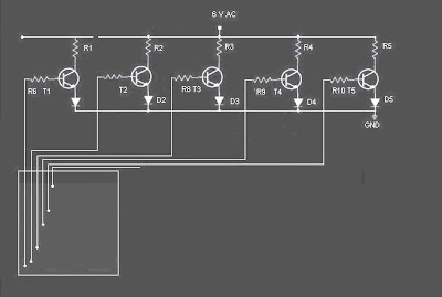
This is the circuit diagram of a simple Water level detection (Pendeteksi|Sensor Ketinggian Level Air) for home and industries. In fact the the level of any conductive non corrosive liquids can be measured using this circuit. Pendeteksi|Sensor Ketinggian Level Air is based on 5 transistor switches.Each transistor is switched on to drive the corresponding LED , when its base is supplied with current through the water through the electrode probes.

One electrode probe is (F) with 6V AC is placed at the bottom of tank. Next probes are placed step by step above the bottom probe. When water is rising the the base of each transistor gets electrical connection to 6V AC through water and the corresponding probe. Which in turn makes the transistors conduct to glow LED and indicate the level of water. The ends of probes are connected to corresponding points in the circuit as shown in circuit diagram. Insulated Aluminum wires with end insulation removed will do for the probe. Arrange the probes in order on a PVC pipe according to the depth and immerse it in the tank. AC voltage is use to prevent electrolysis at the probes. So this setup will last really long. I guarantee at least a 2 years of maintenance free operation.That’s what I got and is still going.


Circuit of Water Level
Skema Rangkaian Sensor Ketinggian Level Air


list Components of Water level Detection
  • T1 - T5 BC 548 or 2N2222
  • R1-R5 2.2K 1/4 W
  • R6-R10 22K 1/4 W
  • D1 - D5 LED’s

Use a transformer 6V 500 mA for power supply. Do not use a rectifier! we need pure AC. Use good quality insulated Aluminum wire for probes. If Aluminum wires are not available try Steel or Tin. Copper is the worst. Try the circuit first on a bread board and if not working properly, make adjustments with the resistance values . This is often needed because conductivity of water changes slightly from place to place.

READMORE...

Sunday, August 09, 2009

Rangkaian Pendeteksi obyek Dengan Infra Red

Infra red (infra red) is the diffraction wavelength elektromagnet more than its visible light is between 700 nm and 1 mm. Infra red rays of light is not visible. If viewed with the light spektroskop the infra red light radiation will be visible on the spectrum elektromagnet with wavelength on the wavelength red light. With this long wave infra red light so it will not appear by the heat radiation, but it still feels embossed / detected.

because the infra red is not visible by naked eye so the idea arose to create a tool pendeteksi movement using infra red this

in the image below is the following circuit diagram of an infrared motion detector that can be used to sense intrusions. Infra red rays reflected from a static object will be in one phase, and the rays reflected from a moving object will be in another phase.The circuit uses this principle to sense the motion.

Rangkaian Infra redSkema Rangkaian Pendeteksi obyek Dengan Infra Red

how to work a circuit of Pendeteksi obyek Infra Red
NE 555 is wires as an astable multivibrator . IR diode connected at the output of this IC produces infrared beams of frequency 5Khz. These beams are picked by the photo transistor Q1 . At normal condition ie; when there is no intrusion the output pin (7) of IC2 will be low. When there is an intrusion the phase of the reflected waveforms has a difference in phase and this phase difference will be picked by the IC2. Now the pin 7 of the IC 2 goes high to indicate the intrusion. An LED or a buzzer can be connected at the output of the IC to indicate the intrusion.

Note:
  • Comparators IC2a and IC2b are belonging to the same IC2 (LM1458).
  • When there is disturbance in the air or vehicles passing nearby, the circuit may get false triggered.
  • POT R5 can be used for sensitivity adjustment.

READMORE...

Thursday, August 06, 2009

Rangkaian Pendeteksi Air Hujan sederhana

Rangkain Pendeteksi Air Hujan

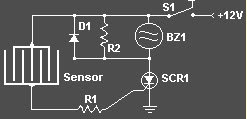
circuit of rain detector uses a sensor made of a small piece of etched PC board and a simple SCR circuit to detect rain and sound a buzzer. The SCR could also be used to activate a relay, turn on a lamp, or send a signal to a security system.

rain detector circuitCircuit of rain detector


Component list of rain detector
  • R1 1K 1/4 W Resistor
  • R2 680 Ohm 1/4 W Resistor
  • D1 1N4001 Silicon Diode
  • BZ1 12V Buzzer
  • S1 SPST Switch
  • SCR1 C106B1 SCR 106CY
  • SENSOR
The sensor is a small piece of PC board etched to the pattern showen in the schematic. The traces should be very close to each other, but never touching. A large spiral pattern would also work.

Make sure to use a loud buzzer.

READMORE...
 
Skema Rangkaian Elektronika