Showing posts with label Remote Control. Show all posts

Wednesday, May 26, 2010

Rangkaian Infra Red Remote Tester

Infra Red Remote Tester

The circuit is very effective to test the remote controls what still works or not, the remote record will be tested using infra red. Examples of the TV remote, AC and others. Please try I am sure 100% will be successful.

Rangkaian Remote TesterRangkaian Remote Tester

The workings of the circuit is very simple, when the infra red sensor receive infrared signals pin 2 sensor will produce a voltage, this voltage will drives the PNP transistor so that the LED lamp and piezo disc (BZ) is active. for the power supply you can use a 9 volt battery and then use IC 7805 or use 1.5 volt batteries x 3

Following the specification of components installed
  • Transistor BC557
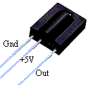
  • TSOP 1738 Sensor Infra Red
  • R1 = 10k ohm ¼ watt Resistor
  • R2 = 1k ohm ¼ watt Resistor
  • R3 = 1k ohm ¼ watt Resistor
  • BZ = piezo disc
  • led
TSOP 1738 Sensor Infra Red


Features
  • Photodetector and preamplifier circuit in the same casing.
  • Receives and amplifies the infrared signal without any external component.
  • 5 V output (active at level 0).
  • 38 kHz integrated oscillator.
  • High sensitivity.
  • High level of immunity to ambient light.
  • Improved shielding against electrical field interference.
  • TTL and CMOS compatibility.
  • Applications: infrared remote control.
Technical specification
  • Supply: 5 V
  • Power consumption: 0.4 to 1.0 mA
  • Min. Ee irradiation: 0.35 mW/m2 typ.
  • Angle of detection: 90
  • Dimensions of the casing (mm): 12.5 x 10 x Thickness 5.8
  • Temperature range: -25 C to +85 C

READMORE...

Friday, October 09, 2009

Rangkaian Remote Control Ultrasonic

This is a remote control circuit employing ultrasonic signals. The ultrasonic transmitter circuit is build around IC1(NE 555). IC1 is an astable multi vibrator operating at 40KHz.The output of IC1 is amplifier the complementary pair of transistors ( Q1 & Q2) and transmitted by the ultrasonic transmitter K1. The switch S1 is used activate the transmitter.

remote ultrasonicSkema rangkaian remote Control ultrasonic


Note:
  • switch S1 can be a push button switch.
  • The preset R16 can be used to adjust the sensitivity of the receiver.
  • The frequency of the ultrasonic signal can be varied by adjusting the preset R17.Adjust it for optimum performance.


The ultrasonic receiver uses an sensor transducer (K2) to sense the ultrasonic signals. When an ultrasonic signal is falling on the sensor, it produces a proportional voltage signal at its output. This weak signal is amplified by the two stage amplifier circuit comprising of transistors Q3 and Q4.The output of the amplifier is rectified by the diodes D3 & D4.The rectified signal is given to the inverting input of the opamp which is wired as a comparator. When ever there is an ultrasonic signal falling on the receiver, the output of the comparator activates the transistors Q5 & Q6 to drive the relay. In this way the load connected via the relay can be switched. The diode D5 is used as a free wheeling diode.


Features IC CA3140


  • Very High Input Impedance (ZIN) -1.5TΩ (Typ)
  • Very Low Input Current (Il) -10pA (Typ) at ±15V
  • Wide Common Mode Input Voltage Range (VlCR) - Can be wung 0.5V Below Negative Supply Voltage Rail
  • Output Swing Complements Input Common Mode
  • Directly Replaces Industry Type 741 in Most Applications
  • Pb-Free Plus Anneal Available (RoHS Compliant)


Pin Connection Ic NE 555


  • Ground, is the input pin of the source of the negative DC voltage
  • Trigger, negative input from the lower comparators (comparator B) that maintain oscillation capacitor voltage in the lowest 1 / 3 Vcc and set RS flip-flop
  • Output, the output pin of the IC 555.
  • Reset, the pin that serves to reset the latch inside the IC to be influential to reset the IC work. This pin is connected to a PNP-type transistor gate, so the transistor will be active if given a logic low. Normally this pin is connected directly to Vcc to prevent reset
  • Control voltage, this pin serves to regulate the stability of the reference voltage negative input (comparator A). This pin can be left hanging, but to ensure the stability of the reference comparator A, usually associated with a capacitor of about 10nF to berorde pin groun
  • Threshold, this pin is connected to the positive input (comparator A) which will reset the RS flip-flop when the voltage on the capacitor from exceeding 2 / 3 Vc
  • Discharge, this pin is connected to an open collector transistor Q1 is connected to ground emitternya. Switching transistor serves to clamp the corresponding node to ground on the timing of certain
  • Vcc, pin it to receive a DC voltage supply. Usually will work optimally if given a 5-15V. the current supply can be seen in the datasheet, which is about 10-15mA.
.

READMORE...

Monday, August 17, 2009

Rangkaian Remote Control IC 555

Remote Control menggunakan IC 555

Ic 555 is an integrated circuit (chip) implementing a variety of timer and multivibrator applications. The IC was designed by Hans R. Camenzind in 1970 and brought to market in 1971 by Signetics (later acquired by Philips). The original name was the SE555 (metal can)/NE555 (plastic DIP) and the part was described as "The IC Time Machine". It has been claimed that the 555 gets its name from the three 5-kohm resistors used in typical early implementations, but Hanz Camenzind has stated that the number was arbitrary The part is still in wide use, thanks to its ease of use, low price and good stability. As of 2003 it is estimated that 1 billion units are manufactured every year.

Depending on the manufacturer, the standard 555 package includes over 20 transistors, 2 diodes and 15 resistors on a silicon chip installed in an 8-pin mini dual-in-line package (DIP-8).

The 556 is a 14-pin DIP that combines two 555s on a single chip. The 558 is a 16-pin DIP that combines four slightly modified 555s on a single chip (DIS & THR are connected internally, TR is falling edge sensitive instead of level sensitive).

Also available are ultra-low power versions of the 555 such as the 7555 and TLC555. The 7555 requires slightly different wiring using fewer external components and less power.


The connection of ic 555 as follows:
  • GND(1)Ground, low level (0V)
  • TRIG(2)A short pulse high-to-low on the trigger starts the timer
  • OUT(3)During a timing interval, the output stays at +VCC
  • RESET(4)A timing interval can be interrupted by applying a reset pulse to low (0V)
  • CTRL (5)Control voltage allows access to the internal voltage divider (2/3 VCC)
  • THR (6)The threshold at which the interval ends (it ends if U.thr → 2/3 VCC)
  • DIS (7)Connected to a capacitor whose discharge time will influence the timing interval
  • V+, VCC(8) The positive supply voltage which must be between 3 and 15 V

READMORE...

Saturday, August 15, 2009

Rangkaian Radio Remote Control Mobil Mainan

Rangkaian Remote Control Mobil Mainan

In this system, radio signals emanated not continue to be raised but only when the controller sends the right / left or forward / backward, that is only a radio frequency that discontinuous,so that the credit delivery frequency radio waves.

The amount of credit that is sent to represent the command post, the forward was represented with 8 credits, left represented with 16 credits, 32 credits right and Backward 64 credits. Commands can be sent is a combination of 2 commands, namely the combination of forward / backward and right / left, as an example can be sent forward and the left, in this case the amount of credit that is sent 24, the Answer of the forward and the balance of 8 the left as many as 16 credits.


Making transformer TX and RX:
Transformer T1 in series transmitter and recipient, is the same, and must be made. Transformer was built using plastic koker transformer (spare part radio) so that the step appears to have 5 channels that can be filled with a wire coil, as shown in the picture. Wearing this koker facilitate scrolling wire transformer. If it can not be koker like that, just use the normal. Koker transformer is small and ferit is also small (3 mm) as the first assembly is often used for CB 27 MHz radio.

Transformer wire to wire to use in the unloading of koker, and slowly open the wire coil inside the existing wire koker because it is quite smooth and easy to drop out
  • coil wire from the foot of the number to 5 feet 4 hours direction (CW) of 3-and-roll at level 1 (line at the bottom line above)
  • Scroll through the wire from 1 foot to 2 feet clockwise roll of 4 on the exact level 2.
  • Continue to roll (from step 2) clockwise a quarter roll of 3 to 3 feet in three levels. (You can set exactly a quarter roll, because the path that has kokernya be split into 4).
Making coil L1
Scroll through the copper wire diameter size of 0.3 - 0.5 mm of 10 quarter roll koker in diameter about 4 mm (which will be released later) is also clockwis

Making coil L2
Scroll through the copper wire diameter of 0.1 mm sizes of 50 on the roll without koker plastic ferit diameter about 3.5 - 4 mm (search item from the plastic material used) is also clockwise. The length of the coil along liputi in 5 mm.

READMORE...

Tuesday, June 16, 2009

Remote Control infra Merah Sederhana

By using the NE 555 and LM 567, we can make the system infra red remote control. Remote control works based on this reading frequency signal that is sent, so that the transmitter frequency signal must be the same as the receive frequency. Frequency on the remote control transmitter is determined by the value R1 and C1 based on the following equation:


Skema Rangkaian Remote Control Transmitter

As mentioned above, the remote control must have the same frequency with the frequency transmitted by the transmitter chain. Recipient of this frequency range can be determined with the following equation:


Skema Rangkaian penerima Remote Control

To simplify the process of tunning, R1 at the recipient install a remote control in the variable resistor (VR). while the transmitter constant value (resisitor tetep / normal). If a circuit of remote control has been completed on the raft, to know whether a circuit of working well, the first step must be done is make tunning, with the transmitter is turned on continuously, while R1 is set so that the recipient can detect the signal transmitter. If the tuning is successful, the relay recipient akan romote control switch position (nye-Tech), when it has happened means that a circuit of remote control is working well. to the next can try pressing the switch on the remote control at the sender (transmitter). should switch on when the press kutup relay at the remote recipients will move kutup (nye-Tech).


READMORE...

Friday, May 29, 2009

simple circuit of infra red remote control

By using the NE 555 and LM 567we can create a system of remote control via infra red light media. This system works based on the frequency of reading the signal transmitted, so that the frequency of the signal transmitter in the series must be the same as the receiving frequency.
Frequency on the transmitter is determined by the value of R1 and C1 based on the following equation:


infra red remote control Transmitter

As mentioned above, the recipient must also have the same detection frequency with a frequency that transmitted by a circuit of transmitter. Frequency of a circuit of receiver is determined by the following equation:


infra red remote control Reciever

To simplify the process of tunning, R1 on the part of the receiver is a variable resistor. while at the transmitter is still valuable. When the series was ready, so that the system can work well, the first step is to do tunning, with the way the transmitter is turned on continuously, while R1 is set in the value until the recipient can detect the signal transmitter

READMORE...
 
Skema Rangkaian Elektronika