Showing posts with label Tester Circuits. Show all posts

Wednesday, December 29, 2010

High Voltage Meter or Probe Design

Common voltmeters, digital or analog, usually range to some hundred volts maximum. Higher voltages not only cannot be indicated, but will also destroy the instrument. However, the range of any voltmeter can easily be extended using extra series resistance, as shown in the figure. Calculating the necessary resistance implies knowledge of the input impedance of the voltmeter.

High Voltage Meter or Probe Circui
Circuit and formula for constructing high voltage probes. For example, let's assume we want to extend the range of a standard digital voltmeter (input impedance 10MOhm) to 100kV. The maximum DC voltage the meter can take is 1000V. This means we need an external 1GOhm high voltage resistor in series with the meter. The total voltage ios given by the value indicatedby the meter, times 100. If we wanted to read the voltage in kV directly, we would need a resistor 1000 times as large as the input impedance of the voltmeter, i.e. 10GOhm.

Such home-brew high voltage probes are good for DC only. For AC voltages, capacitive input impedance of the meter and capacity of the probe must be matched, which is difficult to achieve because of parasitic capacitance of the resistor chain. A few pF (the capacitance of a 1cm radius metallic sphere) make a big difference, especially at higher frequencies.

Source: kronjaeger.com

READMORE...

Rangkaian Transistor Tester

The circuit shown below is a simple circuit transistor tester. In some digital and analog avometer now mostly been contained this feature, but it can not hurt us a little more creative. This circuit can also be used to detect whether a transistor is NPN / PNP.

Rangkaian Transistor TesterSkema Rangkaian Transistor Tester

Circuit operation is as follows. The 555 timer is set up as a multi-vibrator 12hz. The output on pin 3 drives the 4027 flip-flop. This flip-flop divides the input frequency by two and delivers complementary voltage outputs to pin 15 and 14. The outputs are connected to LED1 and LED2 through the current limiting resistor R3. The LED's are Arranged so Pls That the polarity across the circuit is one way only one LED will from light and Pls the polarity reverses the other LED light earnest, therefore Pls no transistor is connected to the tester the LED's will from alternately flash. Also The 4027 outputs are connected to resistors R4 and R5 with the junction of these two resistors connected to the base of the transistor being tested. With a good transistor connected to the tester, the transistor will of turn on and Produce a short across the LED pair. If a good NPN transistor is connected then LED1 will from flash by Itself and if a good PNP transistor is connected then LED2 will from flash by Itself. If the transistor is open both LED's will from flash and if the transistor is shorted then neither LED will from flash.

IC NE555 PinoutIC NE555 Pinout

IC 4027 PinoutIC 4027 Pinout

READMORE...

Saturday, December 18, 2010

Rangkaian Ampere Meter Digital

This is a circuit of a digital ampere meter with 4 digit LED 7-segment display, the circuit capable of measuring the current consumption up to 10A with selected 100mA, 10mA and 1mA accuracy, and consumes only about 25mA of current. The ammeter is based on single ICL7107 chip and 3.5-digit seven segment LED displays. Due to a Relatively small number of components That the circuit is using it is possible to fit it on a small 3cm x 7cm printed circuit board.

Rangkaian Ampere Meter DigitalSkema Rangkaian Ampere Meter Digital

0.01 Ohm resistor should be made out of 1.5mm thick / 5cm long copper wire. 0.1 Ohm and 1 Ohm resistors should have 5W ratings.

For highest accuracy it is recommended that the ICL7107 ampere meter module should be supplied with its own voltage supply. If measurement of the current of the same supply is needed, ICL7107 ampere meter would have to sample negative not positive voltage supply.

Brightness of the LED displays can be varied by adding or removing 1N4148 small signal diodes that are connected in series. Use two 1N4148 diodes for higher brightness.

Also, the use of 7805 5V voltage regulator is highly recommended to prevent the damage of ICL7107 and 7660 ICs. .

Source: http://electronics-diy.com

READMORE...

Power Meter Schematic For Audio Amplifier

This is a simple schematic of audio power meter using LM3915 IC, this schematic can be used to measure the actual output power of your amplifier. For an audio engineer, this schematic Seems to be very helpful, especially for checking of sound system installation and field testing. Due to its logarithmic scale, the wide range of audio output with only ten scales cans Also be measured. If you take an attention to the pin number 5 of the LM3915, see That you will from the input is not yet Rectified. At this input pin, the negative swing will from the present. However, it is harmless since the current is limited by R1, the LM3915 earnest therefore respond only to positive cycle.
Power Meter Schematic Schematic of Power Meter For Audio Amplifier

Note:
When the speaker resistance is 4Ω, then, make R1=10kΩ, if the resistance of speaker is 8Ω, make R1=8kΩ, and if the resistance of speaker is 16Ω, make R1=30kΩ.

The absence of peak detector or the detector will of averages give the circuit a fast reading of instantenous power, and this Gives us insight of both average and peak condition. For more readable peak or average mesurement, you cans use peak or average detector circuit.

source : national semiconductor application notes

READMORE...

Sound Level (Decibel) Meter Circuit

This is a decibel meter electronic circuit, For an audio engineer, this circuit seems to be very helpful, especially for checking of sound pressure levels from about 60 to 70 Decibel (dB). EACH light represents about a 3dB change in sound level so That Pls all three lights are on, the sound level is about 4 times Greater than the level needed to light one lamp. The sensitivity cans be adjusted with the 500K pot so That one lamp comes on with a reference sound level. The other two lamps will from then indicate about a 2X and 4X increase is in volume.
Sound Level (Decibel) Meter CircuitCircuit of Sound Level (Decibel) Meter

In operation, with no input, the DC voltage at pins 1,2 and 3 of the op-amp will be about 4 volts, and the voltage on the (+) inputs to the 3 comparators (pins 5,10,12) will be about a half volt less due to the 1N914 diode drop. The voltage on the (-) comparator inputs will be around 5.1 and 6.5 which is set by the 560 and 750 ohm resistors.

When an audio signal is present, the 10uF capacitor connected to the diode will charge toward the peak audio level at the op-amp output at pin 1. As the volume increases, the DC voltage on the capacitor and also (+) comparator inputs will increase and the lamp will turn on when the (+) input goes above the (-) input. As the volume decreases, the capacitor discharges through the parallel 100K resistor and the lamps go out. You can change the response time with a larger or smaller capacitor.

Source: www.bowdenshobbycircuits.info

READMORE...

Wednesday, May 26, 2010

Rangkaian Infra Red Remote Tester

Infra Red Remote Tester

The circuit is very effective to test the remote controls what still works or not, the remote record will be tested using infra red. Examples of the TV remote, AC and others. Please try I am sure 100% will be successful.

Rangkaian Remote TesterRangkaian Remote Tester

The workings of the circuit is very simple, when the infra red sensor receive infrared signals pin 2 sensor will produce a voltage, this voltage will drives the PNP transistor so that the LED lamp and piezo disc (BZ) is active. for the power supply you can use a 9 volt battery and then use IC 7805 or use 1.5 volt batteries x 3

Following the specification of components installed
  • Transistor BC557
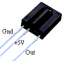
  • TSOP 1738 Sensor Infra Red
  • R1 = 10k ohm ¼ watt Resistor
  • R2 = 1k ohm ¼ watt Resistor
  • R3 = 1k ohm ¼ watt Resistor
  • BZ = piezo disc
  • led
TSOP 1738 Sensor Infra Red


Features
  • Photodetector and preamplifier circuit in the same casing.
  • Receives and amplifies the infrared signal without any external component.
  • 5 V output (active at level 0).
  • 38 kHz integrated oscillator.
  • High sensitivity.
  • High level of immunity to ambient light.
  • Improved shielding against electrical field interference.
  • TTL and CMOS compatibility.
  • Applications: infrared remote control.
Technical specification
  • Supply: 5 V
  • Power consumption: 0.4 to 1.0 mA
  • Min. Ee irradiation: 0.35 mW/m2 typ.
  • Angle of detection: 90
  • Dimensions of the casing (mm): 12.5 x 10 x Thickness 5.8
  • Temperature range: -25 C to +85 C

READMORE...

Sunday, May 23, 2010

Rangkaian Pengukur Jarak

This circuit Can be Used to Measure distance covered by bicycle using a reed switch as the sensor and use the magnet tied to a wheel. Detection of rolling is then made by a proximity effect, Pls the magnet close to the reed switch. This close / open reed switch contact Can use to make on-off signal. 68HC908QY4 microcontroller function for counting the pulse signal Produced by reed switches, and then Direct display in meter unit through lcd 16 x 1 line LCD

 Pengukur Jarak Prototipe Pengukur Jarak Prototipe

Rangkaian Pengukur JarakSkema rangkaian pengukur jarak

To Interface signals for LCD are D4-D7, RS and E. 4-bit It was interfacing, no busy checking. D0-D3 and R / W # is not Used, so We must tie to GND. Since We Can not check Busy bit, so the delay routine must be ready LCD Used to wait for command and writing data. The sensor inputs are PTA2 for reed switch contact and PTA0 for 0 / +5 V analog input can use a small phone jack for both sensors. in the image below shows a sample sensor and cable making. Later shrinkage tube We need to protect the sensor. The position sensor Pls Pls fix to the bicycle wheel Also Important. We need the magnetic flux perpendicular to the contact.

sensor and cable making

Software/program

Software for write to68HC908QY4 microcontroller is s-record.hex ,which was written by C-language ,the source code is firmware source code.

source http://chaokhun.kmitl.ac.th

READMORE...

Sunday, May 16, 2010

Rangkaian Thermometer Berbasis Mikrokontroler AT89S52

This is a circuit of a microcontroller AT89S52 Thermometer and 12-bit ADC LTC1298, programs written in the language c program with digital filtering and interface the LED display. The reading provides 0.1C sensitivity.

The hardware block and circuit diagram is shown in Fig below. The sensor is epoxy molded thermistor. The circuit for signal conditioning is a simple voltage divider. The ADC is 12-bit SPI interface LTC1298 analog-to-digital converter. The microcontroller is Atmel 89S52. The display has four digits 0.5 inches 7-segment LED. The segment driver provides 32-bit CMOS output.

Rangkaian Thermometer Berbasis Mikrokontroler AT89S52
Skema Rangkaian Thermometer Berbasis Mikrokontroler AT89S52

Rangkaian Thermometer Berbasis Mikrokontroler AT89S52
Thermometer Block Diagram

The ADC is 12-bit (LTC1298 or MC3202) are two channels, CH0 and CH1. The input signal from thermistor for ADC channel 0 is simple voltage divider. Channel1 is available for other sensor. The sample shown in schematic is HIH-3160 Honeywell Relative Humidity Sensor. The ADC chip is interfaced with MCU, 89S52 with P1.1, P1.2 and P1.3. The display has 4-digit LED. The 4094 CMOS shift register drives the LED directly.


Software

The main function is time triggered by 10ms timer0 running. The ADC is updated on LED every 10 ticks.

while(1)
{
while(!cputick)
continue;
cputick=0;
print_ADC();
}

The function that reads 12-bit data from ADC is read_ADC(char n). The function has two loops. First loop is to send 4-bit command. And the second loop is 12-bit to shift the data from ADC.

sbit Data = P1^1;
sbit CLK = P1^2;
sbit CS = P1^3;


int read_ADC(char n)
{ int k;
char i,channel;
k=0;
CS=0;
if(n==0) channel=0x0d;
else channel=0x0f;

for(i=0;i<4;i++) clk =" 0;" data =" 1;" data =" 0;" clk =" 1;" data =" 1;" clk =" 0;" i="0;i<12;i++)" clk="1;" clk="0;" cs =" 1;">

To provide smooth reading, I added the 5-point moving average to the raw data. The function low_pass_filte1( ) is used to filter the high frequency noise. The reading is calibrated to degree Celsius with Platinum 100 standard thermometer. We found the equation y=0.0323x-15.122.

int low_pass_filter1(void)
{
x5=x4;
x4=x3;
x3=x2;
x2=x1;
x1=read_ADC(0);
return(x1+x2+x3+x4+x5)/5;
}

float read_temp1_filter(void)
{
return(0.0323*low_pass_filter1()-15.122);
}


READMORE...

Sunday, May 09, 2010

Rangkaian Battery Tester ( Penguji Battery)

This circuit can be used to test the battery without the need of power supply or expensive moving-coil voltmeters. It has two Ranges: Pls SW1 is set as shown in the circuit diagram, test the circuit cans 3V to 15V batteries. When SW1 is switched to the other position, only 1.5V cells Can be tested.

Rangkaian Battery Tester ( Penguji Battery)Skema Rangkaian Battery Tester ( Penguji Battery)

List Component:

R1______________2K2 1/4W Resistor
R2______________3R3 1/4W Resistor
R3_____________10R 1/4W Resistor
R4______________4K7 1/4W Resistor
R5_____________33K 1/4W Resistor
R6,R7_________100K 1/4W Resistors
R8____________220K 1/4W Resistor
R9____________330K 1/4W Resistor
R10___________500K Trimmer Cermet
C1,C2__________10nF 63V Polyester Capacitors
C3-C7_________100nF 63V Polyester Capacitors
C8____________220µF 35V Electrolytic Capacitor
D1,D7___________LEDs Red 5mm. (see Notes)
D2-D6________1N4148 75V 150mA Diodes
Q1___________2N3819 General purpose FET
Q2,Q3_________BC337 45V 800mA NPN Transistors
IC1,IC2________7555 or TS555CN CMos Timer ICs
P1_____________SPST Pushbutton
SW1____________DPDT Switch
BUT____________Battery under test

Testing 3V to 15V batteries:
  • Switch SW1 as shown in the circuit diagram.
  • Place the battery under test in a suitable holder or clip it to the circuit.
  • Wait some seconds in order to let C8 reach its full charge.
  • LED D1 illuminates at a constant intensity, independent of battery voltage.
  • If D1 illuminates very weakly or is fully off the battery is unusable.
  • If D1 has a good illumination, press P1 and keep an eye to LED D7. If D7 remains fully off, the battery is in a very good state.
  • If D7 illuminates brightly for a few seconds, the battery is weak. This condition is confirmed by a noticeable weakening of D1 brightness.
  • If D7 illuminates weakly for a few seconds but D1 maintain the same light intensity, the battery is still good but is not new.
Testing 1.5V batteries:
  • Switch SW1 in the position opposite to that shown in the circuit diagram.
  • Place the battery under test in a suitable holder or clip it to the circuit.
  • Wait some seconds in order to let C8 reach its full charge.
  • LED D1 illuminates very weakly only in presence of a new battery, otherwise is off.
  • Press P1 and keep an eye to LED D7. If D7 remains fully off the battery can be in very good state.
  • If D7 illuminates brightly for a few seconds, the battery is weak.
  • If D7 illuminates weakly for a few seconds, the battery is still good but is not new.
  • If you are suspecting a 1.5V cell to be completely discharged, a better test can be made wiring two 1.5V batteries in series, then running the 3V test.

The TS555 is a single CMOS timer which offers very low consumption and high frequency (f(max.) TS555 = 2.7MHz - f(max.) NE555 = 0.1 MHz) Thus, either in Monostable or Astable mode, timing remains very accurate.

IC TS555 PinningIC TS555 Pinning

The TS555 provides reduced supply current spikes during output transitions, which enables the use of lower decoupling capacitors compared to those required by bipolar NE555. Timing capacitors can also be minimized due to high input impedance (1012 W).

Maximum rating ic
Supply Voltage: +18 V
Junction Temperature: +150 oC

Source

READMORE...

Tuesday, March 02, 2010

Rangkaian Audio Signal Injector|Tracer

This circuit can be used as a signal injector or signal tracer. This circuit is very helpful in trouble shooting audio circuits, when you need to test a circuit by injecting a signal and observe the output (by watching the oscilloscope or by hearing the loudspeaker ), or by tracing some points inside the circuit when an audio signal is applied to the input.

Rangkaian Audio Signal Injector|TracerSkema Rangkaian Audio Signal Injector|Tracer

The circuit uses supply from 9 volts battery. An alligator clip is recommneded for the ground probes, so you can works with one hand to hold the board, and the other hand to target the test probes. The SPDT switch connected to the transitor and the earpiece is used to select the function, whether as a signal or a signal injector tracer.


Transistor 2n3904

This transistor is designed as a general purpose amplifier and switch. The useful dynamic range extends to 100 mA as a switch and to 100 MHz as an amplifier.
Transistor 2n3904 Pin

Absolute maximum rating
  • Collector-Emitter Voltage 40 V
  • Collector-Base Voltage 60 V
  • Emitter-Base Voltage 6.0 V
  • Collector Current - Continuous 200 mA
  • Operating and Storage Junction Temperature Range -55 to +150 °C

READMORE...

Monday, March 01, 2010

Rangkaian Pengukur Induktansi (Inductance Meter)

Inductor

An inductor is a passive electronic component that can store energy in magnetic fields generated by electric current through it. Inductor's ability to store magnetic energy is determined by induktansinya

Inductance (L) (measured in Henry) is the effect of the magnetic field formed around the current carrying conductor that is holding the current changes. The electric current through the conductor makes the magnetic field is proportional to the magnitude of the flow. Changes in the flow causes the magnetic field changes that result in the opposite electromotive force induced by GGL that are against changing the current.

Rangkaian Pengukur Induktansi (Inductance Meter )

This inductance meter is capable of measuring inductor value. Inductance meter is very helpful in designing coil by hand and measure the inductance from trial and error to get the required value. The Inductance meter is designed to provide twi measurement range. The low range will measure inductors with inductance value between 3uH to 500uH, and the high range will measure inductance values between 100uH and 5mH.

Rangkaian Pengukur Induktansi
Skema Rangkaian Pengukur Induktansi

To calibrate this inductance meter adapter, connect a digital voltmeter, swith the voltmeter to 200 mV range, short the test probe and adjust the zero (R1) to give zero millivolt reading on your digital voltmeter. To calibrate the low range of this inductance meter adapter, switch the voltmeter to low range position, and select 2 V range for the digital voltmeter. Test a known inductor that has value around 400uH, adjust the low calibration pot to give correct reading of 1mV / uH. If you use a 400uH inductor then you must adjust the calibration to give exactly a 400mV reading. For high range calibration, switch the range selector to high position and use a known inductor around 5 mH, adjust the high calibration pot to give 100mV per mH. A 5 mH inductor should give a 500mV reading on your DVM.

READMORE...

Sunday, February 21, 2010

Rangkaian Pengukur Kapasitas Kapasitor (Kapasitas Meter)

Capacitor or often referred to as the capacitor is a device that can store energy in electric fields, collected by an internal imbalance of electric charge. Capacitor has a unit called the Farad. Identified capacitor has two legs and two poles of positive and negative and has a liquid electrolyte and usually cylindrical. Whereas the other species most of the lower capacity values, do not have a positive or negative poles on foot, mostly flat, round brown, red, green and others such as tablets or buttons.
Kapasitor
Rangkaian Pengukur Kapasitas Kapasitor

This capacitance meter circuit which can be used to measure the size of the capacitor capacity.
This circuit uses pnp transistors, you can use almost any pnp transistors with frequency bandwidth of 100MHz and collecttor og current handling capability of 100 mA to replace the transistor if you can find the exact type as shown in the Schematic diagram
Rangkaian Pengukur Kapasitas Kapasitor Skema Rangkaian Pengukur Kapasitas Kapasitor

Note:
  • This circuit can be used supplay voltage 6 VDC.
  • to measure the capacitor can be done by placing a capacitor in the CX

READMORE...

Saturday, February 20, 2010

Rangkaian Penguji FET| Mosfet

MISFET or FET is a related term meaning insulated-gate field-effect transistor, and is almost synonymous with MOSFET. This device used for amplifying or switching electronic signals. The basic principle of the device adalah voltage on the oxide-insulated gate electrode can induce a conducting channel between the two other contacts called source and drain. The channel can be of n-type or p-type, and is accordingly called an NMOSFET or a PMOSFET (also commonly nMOS, pMOS). It is by far the most common transistor in both digital and analog circuits, though the bipolar junction transistor was at one time much more common.

Circuit symbols Mosfet

Rangkaian Penguji FET| Mosfet

This circuit is used to test N-Mosfets, whether it works or not. If it is not working, the LED will not flash. If Mosfet is working it will operate in the astable multivibrator circuit causing the Led to flash.

This circuit can test almost any N-Mosfets As a common emitter buffer that also drives the led as it receives pulses from the Mosfet drain, this circuit uses the NPN transistor


List Component
R1______4.7k Ohm 1/4 watt resistor
R2______470k Ohm 1/4 watt resistor
R3______1M Ohm 1/4 watt resistor
R4______1k Ohm 1/4 watt resistor
R5______47k Ohm 1/4 watt resistor
R6______470 Ohm 1/4 watt resistor
C1______0.1 uF/16 volt Capasitor elektrolit
c2______2.2 uF/16 volt Capasitor elektrolit
TR1_____c9014 NPN transistor
TR2_____c3014 NPN transistor
LED

Absolute maximum ratings Transitor KTC9014

Collector-Base voltage__________ 60 V
Collector-Emitter Voltage_______ 50 V
Emitter-Base voltage____________ 5 V
Collector current_______________ 150 mA
Emitter current_________________ -159 mA
Collector power dissipation_____ 625 mW
Junction temperature____________ 150 C
Storage temperature range_______-55 to 159 c

READMORE...

Tuesday, January 26, 2010

Rangkaian Kristal Tester

Kristal Tester

In the world of electronics using crystal oscilator almost always in use. In the circuit below is a series to test the crystal. (Not measuring frequensy). With this circuit we could find out whether the crystal is still good or not. Test Clip to attach electrodes on crystal (foot), S1 in the press (On) then LED1 will light up if the crystal is still good. if you mendapa difficulties 2N356U transistors can be used with the type of transistor NTE123AP / PN100 / 2N3904.

rangkaian kristal testerSkema rangkaian kristal tester

The mechanism of this crystal tester is very simple. If a good crystal is connected to the test lead, the oscillator will work, and an AC signal will be generated at Q1 emitter. This AC signal will flow through capacitor C3 and trigger the Q2 to light the LED indicator. The diode 1N4148 provide the back path for the AC signal. If the crystal is bad, the oscillator won’t work, and there is only DC voltage level at Q1 emitter. This DC voltage level won’t trigger the Q2 transistor since the capacitor C3 block any DC signal. You can use any high gain high frequency transistor for this crystal tester circuit, in case you can’t find exact transistor series as shown in the schematic diagram.

READMORE...

Rangkaian Kabel (lan) Tester.

Kabel Tester

Circuit of cable tester with a separate LED Will show open circuits, short circuits, reversals, earth faults, continuity and all with four IC's. The circuit comprises transmitter and receiver, the cable under test linking the two. The transmitter is nothing more than a "LED chaser" the 4011 IC is wired as astable and clocks a 4017 decade counter divider. The 4017 is arranged so that on the 9th pulse,the count is reset. Each LED will light sequentially from LED 1 to LED 8 then back to LED 1 etc. As the 4017 has limited driving capabilities, then each output is buffered by a 4050. This provides sufficient current boost for long cables and the transmitter and receiver LED's. The receiver is simply 8 LED's with a common wire.

rangkaian kabel testerSkema rangkaian kabel (lan) tester


Pinning IC 4017


With a good cable and all wires connected then LED 1 will light at both cable ends, followed in sequence by LED 2 ,3, 4 etc to LED 8, the sequence then repeating. If a 4 wire cable is used, it must be connected to use the common. The sequence would be LED 1,2,3,4 repeating with a delay as the 4 unused outputs are stepped through. To check for earth contact faults, the probe labeled "to earth connection" would be physically connected to a local earth. A wire that is earthing will dim or extinguish the LED's at both ends of the cable. An LED not lighting at the receiver, indicates a broken or open circuit.

The LED sequence of course is stepped through, as you know the transmitter "pattern" it is easy to tell the state of the cable by viewing the receiver pattern. The earth condition will only show up if the contact to earth is less than 1000 ohms, a better but more time consuming method for earth faults is to use a meter on the Megaohms range.


Source

READMORE...

Tuesday, December 22, 2009

Rangkaian Speedometer Digital

Speedometer Digital

This circuit serves to show the speed of the vehicle in kmph. An opaque disc is mounted on the spindle attached to the front wheel of the vehicle. The disc has about equidistant holes on its periphery. On one side of the disc an infrared LED is fixed and on the opposite

side of the disc, in line with the IR LED, a phototransistor is mounted. IC LM324 is wired as a comparator. When a hole appears between the IR LED and phototransistor, the phototransistor conducts. Hence the voltage at collector of the phototransistor and inverting input of LM324 go ‘low’, and thus output of LM324 becomes logic ‘high’. So rotation of the speedometer cable results in a pulse (square wave) at the output of LM324. The frequency of this waveform is proportional to the speed.

rangkaian speedometer digitalSkema rangkaian speedometer digital

rangkaian speedometer digital
For a vehicle such as LML Vespa, with a wheel circumference of 1.38 metres, and number of pulses equal to 10 per revolution, we get the relationship:

This speedometer can measure up to 99 kmph with a resolution of 1 kmph. The range can be increased up to 999 kmph by adding another stage consisting of one each of ICs 7490, 74175, 7447 and a 7-segment display.

READMORE...

Wednesday, December 16, 2009

Menentukan B-C-E Transistor Menggunakan Rangkaian.

Menentukan Basis-Collector-Emitter Transistor Menggunakan Rangkaian

Basis-Collector-Emitter Transistor
Testing procedure:

  • Connect randomly the pins of the transistor under test to J1, J2 and J3 sockets or clips.
  • Close SW1, SW2 and SW3.
  • Push on P1; if the transistor is in good health the response of the Identifier will be:
  • Two terminals will show both LEDs illuminated, the remaining one will show a single LED illuminated.
  • If the LED illuminated is Red, the pin connected to the related connector will be the Base of a NPN transistor.
  • If the LED illuminated is Green, the pin connected to the related connector will be the Base of a PNP transistor.
  • Open the switch related to the single illuminated LED: the two terminals showing both LEDs illuminated will change their state and a single LED per terminal will be illuminated. The LED which previously indicated the Base pin will turn-off.
  • If the transistor was previously identified as NPN, the pin connected to the now illuminated Green LED will be the Emitter, whereas the pin connected to the Red LED will be the Collector.
  • If the transistor was previously identified as PNP, the pin connected to the now illuminated Red LED will be the Emitter, whereas the pin connected to the Green LED will be the Collector.

his procedure will suffice for reliable pin identification of most transistor types. In some cases, mainly when low-gain high power transistors are tested, the LED could illuminate faintly and reliable pin identification could be not so easy. Pushing both P1 and P2 will remedy this shortcoming.


Important

Unfortunately, testing Darlington type transistors could lead to some trouble. In fact, the Base pin and the polarity of these transistor types will be correctly shown by the Pin Identifier in the same way as common transistors, but Collector and Emitter pins will be displayed inverted; i.e. if the transistor was previously identified as NPN, the pin connected to the now illuminated Green LED will be the Collector (NOT the Emitter), whereas the pin connected to the Red LED will be the Emitter (NOT the Collector). On the other hand, if the transistor was previously identified as PNP, the pin connected to the now illuminated Red LED will be the Collector (NOT the Emitter), whereas the pin connected to the Green LED will be the Emitter (NOT the Collector).
This is due to the fact that Darlington power transistors usually incorporate on the same chip a reverse-connected diode across Emitter and Collector. Doubts can be easily dissipated pushing on P2: Darlington transistors will cause all two LED pairs related to Emitter and Collector pins to illuminate brightly. On the contrary, common transistors will cause only a faint illumination of the remaining LEDs and, usually, a single LED indicating the Collector pin will illuminate.

READMORE...

Rangkaian pengukur jarak Digital

Pengukur jarak Digital

This circuit measures the distance covered during a walk. Hardware is located in a small box slipped in pants' pocket and the display is conceived in the following manner: the leftmost display D2 (the most significant digit) shows 0 to 9 Km. and its dot is always on to separate Km. from hm. The rightmost display D1 (the least significant digit) shows hundreds meters and its dot illuminates after every 50 meters of walking. A beeper (excludable), signals each count unit, occurring every two steps.

Rangkaian pengukur jarak  Digital

Skema Rangkaian pengukur jarak Digital


Note:
  • Experiment with placement and sloping degree of mercury switch inside the box: this is very critical.
  • Try to obtain a pulse every two walking steps. Listening to the beeper is extremely useful during setup.
  • Trim R6 value to change beeper sound power.
  • Push P1 and P2 to reset.
  • This circuit is primarily intended for walking purposes. For jogging, further great care must be used with mercury switch placement to avoid undesired counts.
  • When the display is disabled current consumption is negligible, therefore SW3 can be omitted.

A normal step was calculated to span around 78 centimeters, thus the LED signaling 50 meters illuminates after 64 steps (or 32 operations of the mercury switch), the display indicates 100 meters after 128 steps and so on. For low battery consumption the display illuminates only on request, pushing on P2. Accidental reset of the counters is avoided because to reset the circuit both pushbuttons must be operated together. Obviously, this is not a precision meter, but its approximation degree was found good for this kind of device. In any case, the most critical thing to do is the correct placement of the mercury switch inside of the box and the setting of its sloping degree.

List Component

R1,R3____22K 1/4W Resistor
R2________2M2 1/4W Resistor
R4________1M 1/4W Resistor
R5,R7,R8__4K7 1/4W Resistor
R6_______47R 1/4W Resistor
R9________1K 1/4W Resistor
C1_______47nF 63V Polyester Capacitor
C2______100nF 63V Polyester Capacitor
C3_______10nF 63V Polyester Capacitor
C4_______10µF 25V Electrolytic Capacitor
D1_______Common-cathode 7-segment LED mini-display (Hundreds meters)
D2_______Common-cathode 7-segment LED mini-display (Kilometers)
IC1______4093 Quad 2 input Schmitt NAND Gate IC
IC2______4024 7 stage ripple counter IC
IC3,IC4__4026 Decade counter with decoded 7-segment display outputs IC
Q1,Q2___BC327 45V 800mA PNP Transistors
P1_______SPST Pushbutton (Reset)
P2_______SPST Pushbutton (Display)
SW1______SPST Mercury Switch, called also Tilt Switch
SW2______SPST Slider Switch (Sound on-off)
SW3______SPST Slider Switch (Power on-off)
BZ_______Piezo sounder
B1_______3V Battery

READMORE...

Friday, December 04, 2009

Rangkaian Penguji (tester) Dioda Zener

This is a circuit of zener diode tester which tests zener diodes with breakdown voltages extending up to 120 volts. The main advantage of this circuit is that it works with a voltage as low as 6V DC and consumes less than 8 mA current.


Rangkain Penguji (tester) Dioda ZenerSkema Rangkain Penguji (tester) Dioda Zener


The circuit can be fitted in a 9V battery box. Two-third of the box may be used for four 1.5V batteries and the remaining one-third is sufficient for accommodating this circuit. In this circuit a commonly available transformer with 230V AC primary to 9-0-9V, 500mA secondary is used in reverse to achieve higher AC voltage across 230V AC terminals. Transistor T1 (BC547) is configured as an oscillator and driver to obtain required AC voltage across transformer s 230V AC terminals. This AC voltage is converted to DC by diode D1 and filter capacitor C2 and is used to test the zener diodes. R3 is used as a seri- es current limiting resistor. After assembling the circuit, check DC voltage across points A and B without connecting any zener diode. Now switch on S1. The DC voltage across A-B should vary from 10V to 120V by adjusting potmeter VR1 (10k). If every thing is all right, the circuit is ready for use.

For testing a zener diode of unknown value, connect it across points A and B with cathode towards A. Adjust potmeter VR1 so as to obtain the maximum DC voltage across A and B. Note down this zener value corresponding to DC voltage reading on the digital multimeter. When testing zener diode of value less than 3.3V, the meter shows less voltage instead of the actual zener value. However, correct reading is obtained for zener diodes of value above 5.8V with a tolerance of 10per cent. In case zener diode shorts, the multimeter shows 0 volts

READMORE...

Saturday, November 28, 2009

Mengukur Kerusakan Fet Dengan Multimeter

Mengukur Kerusakan Fet Dengan Multimeter


FET is divided into two families: Junction FET (JFET) and Insulated Gate FET (IGFET) or also known as Metal Oxide Silicon (or semiconductor) FET (MOSFET). In contrast to the IGFET, the JFET gate terminal forming a diode with the channel (semiconductor material between the Source and Drain). In its function, this makes N-channel JFET to be a solid-state version of the vacuum tubes, which also forms a diode between the grid and cathode. And also, both (JFET and vacuum tubes) work in "depletion mode", both have a high input impedance, and they conduct electrical current under the control of the input voltage.

Mengukur  Kerusakan Fet Dengan Multimeter
Mengukur Kerusakan Fet Dengan Multimeter

Determination of FET performed by investigators x100 range of black and red on the Source Gate. When the needle to deviate, then the FET is kanalP Janis and if not, the FET is the channel N.

Damage to the FET can be observed with a series of pictures. Range is placed on x1k or x10k, potensio at a minimum, the resistance should be small. When potensio rotated to the right, the resistance should be infinite. If this does not happen, then the possibility of FET damaged.

READMORE...
 
Skema Rangkaian Elektronika