Sunday, October 30, 2011

Ukuran Box Subwoofer 10"

This subwoofer box was created to match and aid the 1.618 Hi-Vi 3-way tower loudspeakers. The main focus of the HiVi 10" subwoofer was to reproduce ultra low frequencies that the 1.618 could not reproduce and aid in overall low end musical reproduction. Low, flat and not "boomy" was priority one. This subwoofer project uses the 10" subwoofer driver which can deliver plenty of bottom end.

The enclosure design and model frequency response are shown below.
Ukuran Box Subwoofer 10

Note:
  • 10" 4 ohm subwoofer
  • O-Audio 500 Watt plate amplifier
  • Freq Response: 25Hz up to chosen x-over point.
  • Overall Dimension: 21"x 12.75"x 20"

For more details on how to make it please read more http://diyaudioprojects.com/Speakers/HiVi-DIY-Subwoofer/

READMORE...

4,8W Class-A MOSFET Amplifier

This is very simple Class-A 2SK1058 MOSFET Amplifier circuit. It is easy to build it, Must use supply volte 24V at high current. It produces the most purest sound. I have no idea of distortion levels etc. but it has a very fine grain, and delicately textured quality.
4,8W  Class-A MOSFET Amplifier CircuitSkema Rangkaian 4,8W Class-A MOSFET Amplifier

2SK1058 Pin DiagramThis is one package 2SK1058 N-Channel MOSFET Pin Diagram

The four resistors are 15ohm and 10W each the which I wired two in series for 30 ohms and then the two sets of 30 ohms are wired in parallel to give a total resistance of 15 ohms. These get extremely hot and burn about 30W at idle.


For more detail please read more http://diyaudioprojects.com/Solid/ZCA/ZCA.htm

READMORE...

LM383 - Car Audio Amplifier Circuit

Circuit schematic shows the circuitry for a Class B amplifier with 8 Watt output, based on the LM383 chip. This amplifier circuit suited for automotive applications. High current capability (3.5A) en-ables the device to drive low impedance loads with low dis-tortion. The LM383 is Current Limited and thermally protected. High voltage protection is available (LM383A) the which enables the amplifier to withstand 40V transients on its supply. The LM383 comes in a 5-pin TO-220 package. By National Semiconductor Corporation
Amplifier berbasis LM383 Skema Rangkaian Car Audio Amplifier
berbasis LM383

Note:
That it's advised you use this with a LM383 chip Suitable heatsink.

LM383 chip pin
This is one package pinout of LM383 chip, If you need more pinouts please download LM383's pdf datasheet.

READMORE...

Friday, June 10, 2011

Rangkaian Power Amplifier Blazer 1000 Watt

This is a audio power amplifier Blazer circuit provides up to 1000Watt . This interesting routes many good bass and treble alive. Importantly should choose Power supply source, which has been fairly high voltage class 70Vdc GND -70V 10A is the current low level

Rangkaian Power Amplifier Blazer 1000 WattSkema Rangkaian Power Amplifier Blazer 1000 Watt

The transistors are 2SC3858 (NPN) and 2SA1494 (PNP), and feature high bandwidth, excellent safe operating area, high linearity and high gain. Driver transistors are 2SC5200 (NPN) and 2SA1943 (PNP). All devices are rated at 230V, with the power transistors having a 150W dissipation and the drivers are 50W.

This circuit describes an amplifier, power supply and tests procedures that are all inherently dangerous. Nothing described in this article should even be considered unless you are fully experienced, know exactly what you are doing, and are willing to take full 100% responsibility for what you do. There are aspects of the design that may require analysis, fault-finding and/or modification.

READMORE...

Tuesday, June 07, 2011

500 Watt Inverter 12VDC to 220VAC

The circuit of 500 Watt Inverter 12VDC to 220VAC is made using a transistor. central component of this inverter circuit is a configuration of 2 pieces of transistors Q1 and Q2 which form a circuit of Flip-Flop. The output of the flip-flop Q1 and Q2 then in severance for each pulse to complement each other using a compiled circuit by Q3 and Q4. Output which complement each other is then given to the driver transistors Q5 and Q6 form the transistor 2SC1061. Power Inverters of this circuit is composed using parallel transistors Q7, Q8 and Q7x, Q8x a form of 2N3055 power transistor 10 pieces. schematic a complete of Inverter 500 Watt circuit can be seen as follows.
Rangkaian 500 Watt Inverter 12VDC to 220VACSkema Rangkaian 500 Watt Inverter
12VDC to 220VAC

Step up part of this inverter circuit using a transformer 12VCT/500VA in secondary and primary 0 - 220V. While the frequency is determined by the flip-flop which is set to 50 Hz.

Note:
  • Q7, Q8 and Q7x, Q8x require heat sink.
  • Output power of this dc dc converter is around 500 watts.
  • An optional 40A fuse can be added in circuit to the 12V supply line.
  • T1 can be a 12-CT-12V /250V/40A mains transformer.

READMORE...

12VDC – 220VAC Inverter Using Cmos CD4047

This inverter circuit will convert 12V DC power from battery to 22oV AC as home power replacement. The inverter can be used for small electronic appliances such as lamp, radio, phone charger, disk player etc.
12VDC – 220VAC inverter circuitSkema Rangkaian 12VDC – 220VAC Inverter
Using Cmos CD4047

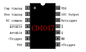
CD4047 Pinout

The inverter circuit has a central component, the CMOS 4047, and converts a 12V DC voltage to 220V AC voltage. 4047 is utilised as a astable multivibrator. At pin 10 and 11 we find a rectangular symmetrically signal which is amplified by tow Darlington transistors T1 and T2 and finally reaches the secondary coil of a transformer network (2 x 10V/100VA). Primary coil terminals voltage is 220 alternative voltage. To obtain a better performance use a toroidal core transformer with reduced losses. With P1 the output frequency can be regulated between certain limits (50…400Hz).


This Circuit From: http://apowersupply.com

READMORE...
 
Skema Rangkaian Elektronika