Tuesday, August 11, 2009

Rangkaian Pendeteksi|Sensor Ketinggian Level Air

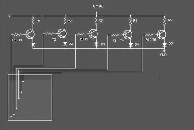
This is the circuit diagram of a simple Water level detection (Pendeteksi|Sensor Ketinggian Level Air) for home and industries. In fact the the level of any conductive non corrosive liquids can be measured using this circuit. Pendeteksi|Sensor Ketinggian Level Air is based on 5 transistor switches.Each transistor is switched on to drive the corresponding LED , when its base is supplied with current through the water through the electrode probes.

One electrode probe is (F) with 6V AC is placed at the bottom of tank. Next probes are placed step by step above the bottom probe. When water is rising the the base of each transistor gets electrical connection to 6V AC through water and the corresponding probe. Which in turn makes the transistors conduct to glow LED and indicate the level of water. The ends of probes are connected to corresponding points in the circuit as shown in circuit diagram. Insulated Aluminum wires with end insulation removed will do for the probe. Arrange the probes in order on a PVC pipe according to the depth and immerse it in the tank. AC voltage is use to prevent electrolysis at the probes. So this setup will last really long. I guarantee at least a 2 years of maintenance free operation.That’s what I got and is still going.


Circuit of Water Level
Skema Rangkaian Sensor Ketinggian Level Air


list Components of Water level Detection
  • T1 - T5 BC 548 or 2N2222
  • R1-R5 2.2K 1/4 W
  • R6-R10 22K 1/4 W
  • D1 - D5 LED’s

Use a transformer 6V 500 mA for power supply. Do not use a rectifier! we need pure AC. Use good quality insulated Aluminum wire for probes. If Aluminum wires are not available try Steel or Tin. Copper is the worst. Try the circuit first on a bread board and if not working properly, make adjustments with the resistance values . This is often needed because conductivity of water changes slightly from place to place.

READMORE...

Sunday, August 09, 2009

Lampu Led Emergency|otomatis, Battery 6 volt

Lampu led emergency|otomatis dengan battery 6 volt

LED (Light Emitting diode) is used almost in most electronic devices such as television, radio cassette, musical instruments, health equipment, testing devices, automotive, and others, as an indicator or signal light.

LED has many advantages rather than the other, such as: The age of a very long life, a power which is very small (energy), the response of a very fast and good.

In 1999 Philips Lumileds Lighting Company is expected to find a LED that can replace the function of light used for illumination. LED light is out with a very bright white. LUXEON LED is called. R & D office located Lumileds in San Jose and Penang (Malaysia). LUXEON presence makes a variety of new opportunities in applications that require bright light with a compact size.

following is the circuit diagram of a low cost emergency based on white light white LED LED. The provide very bright light which turns on when the mains supply is not there. The circuit has an automatic charger which stops charging when the battery is fully charged

Automatic LED Emergency Light Skema Rangkaian Lampu Led Emergency


The IC LM 317 produces a regulated 7 V for the charging of Battery.Transistor BD 140 drives the out put.Transistor BC 548 and Zener diode controls the charging of the battery.

It is always better to connect a heat sink with BD 140.Before using the circuit out put of LM317 must be set to 7V by adjusting the potentiometer.

READMORE...

Rangkaian Pendeteksi obyek Dengan Infra Red

Infra red (infra red) is the diffraction wavelength elektromagnet more than its visible light is between 700 nm and 1 mm. Infra red rays of light is not visible. If viewed with the light spektroskop the infra red light radiation will be visible on the spectrum elektromagnet with wavelength on the wavelength red light. With this long wave infra red light so it will not appear by the heat radiation, but it still feels embossed / detected.

because the infra red is not visible by naked eye so the idea arose to create a tool pendeteksi movement using infra red this

in the image below is the following circuit diagram of an infrared motion detector that can be used to sense intrusions. Infra red rays reflected from a static object will be in one phase, and the rays reflected from a moving object will be in another phase.The circuit uses this principle to sense the motion.

Rangkaian Infra redSkema Rangkaian Pendeteksi obyek Dengan Infra Red

how to work a circuit of Pendeteksi obyek Infra Red
NE 555 is wires as an astable multivibrator . IR diode connected at the output of this IC produces infrared beams of frequency 5Khz. These beams are picked by the photo transistor Q1 . At normal condition ie; when there is no intrusion the output pin (7) of IC2 will be low. When there is an intrusion the phase of the reflected waveforms has a difference in phase and this phase difference will be picked by the IC2. Now the pin 7 of the IC 2 goes high to indicate the intrusion. An LED or a buzzer can be connected at the output of the IC to indicate the intrusion.

Note:
  • Comparators IC2a and IC2b are belonging to the same IC2 (LM1458).
  • When there is disturbance in the air or vehicles passing nearby, the circuit may get false triggered.
  • POT R5 can be used for sensitivity adjustment.

READMORE...

Rangkaian Stop Watch Digital Tampilan 7 Segmen

A digital stop watch built around timer LM555 and 4-digit counter MM74C926 with multiplexed 7-segment LED display. MM74C926 consists of a 4-digit counter, an internal output latch, npn output sourcing drivers for common cathode, 7-segment display and an internal multiplexing circuitry with four multiplexing outputs. The counter advances on negative edge of the clock. The clock is generated by timer LM555. The circuit works off a 5V power supply. It can be easily assembled on a general-purpose PCB. Enclose the circuit in a metal box

with provisions for four 7-segment displays, rotary switch S1, start/stop switch S2 and reset switch S3

First, reset the circuit by pressing S3 so that the display shows "000". Now open switch S2 for the stop watch to start counting the time. If you want to stop the clock, close S2. Rotary switch S1 is used to select the different time periods at the output of the astable multivibrator.

Circuit Diagram of Digital Stop Watch


Skema Rangkaian Stop Watch Digital Tampilan 7 Segmen

7 segment

Seven Segment is 8 pieces of LED array is arranged in such a way that was shaping up to 7 segments and 1 point that can be used to show the pattern numbers and some letters. there are two types of seven-segment LED Seven segment of the Common Anode (CA) and Common Cathode (CC).

Seven Segment

On picture above is the layout, naming seven segment each segment and 8 illustrate the fruit is packed as the LED array LED Common Anoda (CA) and an array of LED Common Cathode (CC). segemen seven controllers can be done directly, or through a pattern such as a driver IC 74LS47 to seven segment CA and 74LS48 to seven segment CC.


READMORE...

Rangkaian pembangkit Gelombang Terkontrol|variabel

Rangkaian pembangkit Gelombang Terkontrol|variabel

ICL8038 is a function generator chip, able of generating triangular, square , sine, pulse and sawtooth waveforms . From these sine, square & triangular wave forms can be made simultaneously. There is the option to control the parameters like frequency ,duty cycle and distortion of these functions. rangkian pembangkit gelombang ini is the best function generator circuit for a beginner to start with and is of course a must on the work bench of an electronics hobbyist. The circuit here is designed to produce waveforms from 20Hz to 2o kHz.The ICL 8038 has to be operated from a dual power supply.

Circuit Diagram & Parts List of Function Generator on show in the picture below.
Circuit of Function Generator Pembangkit Gelombang Sinus/kotak/segitiga dan Gigi gergaji

Notes .

  • frequency output can be adjusted using R7.It must be a 100K Log POT.
  • The duty cycle can be adjusted using R3 , a 1K POT.
  • Distortion owave form can be adjusted using R5 , a 100K POT.
  • Square,triangle & sine waveforms can be obtained simultaneously at pins 9,3,2 respectively.
Datasheet ICL 8038

The ICL8038 waveform generator is a monolithic integrated circuit capable of producing high accuracy sine, square, triangular, sawtooth and pulse waveforms with a minimum of external components. The frequency (or repetition rate) can be selected externally from 0.001Hz to more than 300kHz using either resistors or capacitors, and frequency modulation and sweeping can be accomplished with an external voltage. The ICL8038 is fabricated with advanced monolithic technology, using Schottky barrier diodes and thin film resistors, and the output is stable over a wide range of temperature and supply variations. These devices may be interfaced with phase locked loop circuitry to reduce temperature drift to less than 250ppm/oC.

Features ICL 8038
  • Low Frequency Drift with Temperature . . . . . 250ppm/oC
  • Low Distortion . . . . . . . . . . . . . . . 1% (Sine Wave Output)
  • High Linearity . . . . . . . . . . .0.1% (Triangle Wave Output)
  • Wide Frequency Range . . . . . . . . . . . .0.001Hz to 300kHz
  • Variable Duty Cycle . . . . . . . . . . . . . . . . . . . . . 2% to 98%
  • High Level Outputs. . . . . . . . . . . . . . . . . . . . . . TTL to 28V
  • Simultaneous Sine, Square, and Triangle WaveOutputs
  • Easy to Use - Just a Handful of External Components Required

READMORE...

Friday, August 07, 2009

Rangkaian Counter Up|Down Dengan seven segment

Counter up/Down Dengan seven segment Desimal

This circuit can be used for many purposes. Applications ranging from simple bottles in the belt, display a number in the queue physician practices, the timer display for competition pool, until a little complicated to show the amount of rotation in one minute lap machine.


Important components in the Circuit is the following simple counter 74LS192, and have display driver IC 74LS47 (BCD to 7 segment driver) and the indicator 7 segment LED display common anode. In fact there are other census, such as 4-bit binary counter which can be up to 16 tattoo, but here is the census that is used 10 (decade counter) would be made because the tool is the census decimal.

Main component is an IC 74LS192 up / down decade counter, which is a component that can make a census to 10 (0 to 9) up and down. Component 16 is quite a lot of pins can be found in electronics parts stores. 74LS192 built with some of JK flip-flop and gate-gate logic. Logic transition from 0 to 1 (Low to High) at the UP pin (pin 14), the output BCD (binary code decimal) QA, QB, QC and QD Ascending 1 digits.

Similarly if there is a logic transition on the 0 to 1 DN pin (pin 4), the BCD output down 1 digit. It is a good idea if you explained a little about the rules of the BCD, as there is on the table. This is shown in the table 4-bit binary code QD .. QA-me representasikan code decimal from 0 to 9.

So that can be understood by those who view it, binary code is converted to a 7-segment LED drive by using the IC 74LS47 component. Thus, this Circuit can display the corresponding decimal number. This Circuit is used in the 7 segment LED Anoda Common, where all anoda of each LED segment is connected to one and the Vcc supply. To turn one segment, 7 segment LED pins that must be sinks (short) to ground through a resistor. Resistor that is used is 100 Ohm, and this is enough light to light this LED segment.
Counter Up|Down CircuitSkema Rangkaian Counter up/Down 7 segment Desimal


IC 74LS192 also equipped with a CO output pin (Carry Out) and BO (borrow Out) that each is normally high and work separately. Decimal output transition from 0 to 9 (counting up) will trigger pin CO-issued credit 0 to 1 (Low to High). On the transition from decimal 0 to 9 (counting down), a trigger pin BO-issued credit 0 to 1. Thus, the two outputs can be used as a clock trigger level for the next census. As an example in the Circuit-1 below, 2 units in the IC 74LS192-Cascade to make a census of tens of value and unit. Readers can easily stay on if the census level necessary to create value for the next hundreds, thousands and so on.

Rangkaian Couter Desimal of census work if akan CLR pin = 0 (low). For the input port RESET must be given in the ground or logic 0 in normal circumstances. Reset (display shows the decimal number 0) applies if the CLR pin (pin 14) is a transition from logic 0 to 1. Similarly with the pin and pin UP DN, akan work (counter rise / down) only if there is a transition from 0 to 1 on this pin. Readers need to add aCircuit of switch (key) to a trigger-counter (up / down) and Reset.
READMORE...
 
Skema Rangkaian Elektronika