Monday, December 28, 2009

Sensor Warna TCS230.

Sensor Warna TCS230

TCS230 color sensor is a converter IC to the frequency of light colors. There are two main components of this IC makers, namely photodioda and current to frequency converters. Each color can be drawn from the basic colors. To light, color is the color of the basic constituent Red, Green and Blue, or better known as RGB (Red-Green-Blue).

Photodiode on IC TCS230 array arranged in a 8x8 configuration: 16 Photodiode for red menfilter, 16 Photodiode for the green filter, 16 Photodiode for the blue color filter, and unfiltered Photodiode 16. Photodiode groups which will be used can be arranged through the leg selector S2 and S3.

Sensor Warna TCS230Gambar Sensor Warna TCS230
sample color and composition RGB 8-bit scale.

Table Combination pin function S2 and S3

Photodiode will issue the amount of current is proportional to the level of the basic colors of light that happened. This current is then converted into a signal box with a frequency proportional to the amount of current. Output frequency can be scaled by adjusting the leg selector S0 and S1.

Table Output scaling

Thus, programs that we need to get the RGB composition is a frequency counter program. There are two typical ways to calculate the frequency. The first way: We create a timer berperiode 1 second, and during that period we count how many times a wave box.

in the picture above
1 second place in 1000 wave means the frequency is 1000Hz or 1khz

The second way: We compute how much a period of one wave, then look for the frequency by using the formula
  • F=1/T
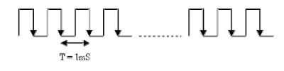
1 full-wave mean period 1mS, frequency: 1/1mS = 1000Hz or 1khz

READMORE...

Friday, December 25, 2009

Fungsi Dan Karakteristik Photodioda BPW41N

Fungsi Dan Karakteristik Photodioda

Photodioda often used as a catcher of light waves emitted by the Infrared. The amount of voltage or electrical current generated by the size depends photodioda radiation emitted by the infrared.

Photodiodes made from semiconductors with a popular material is silicon or gallium arsenide, and others include InSb, Carbuncle, PbSe. This Photodioda (BPW41N) can detect infrared light with wavelengths ranging from 800 to 1100 nm with a peak sensitivity at 950 nm wavelength as shown in the picture below

 Photodioda BPW41N Photodioda BPW41N
Kurva karakteristik photodioda BPW41NKurva karakteristik photodioda BPW41N

When a photon (a unit of light energy) from the light source is absorbed, it is generating an electron and produces a single pair of charge carriers, an electron and a hole where a hole is part of the semiconductor lattice is losing electrons. The direction of current through a semiconductor is opposite to the motion of charge carriers. I was in a Photodiode used to collect photons - causing charge carriers (such as current or voltage) flows / formed in the electrode parts.


Rangkaian Penkondisi Sinyal dari Photodioda

This circuit is used as a current-to-voltage converter by a factor of 1000 times (set by R3) due to backflow photodioda range from 1 to 100 UA the output of U1A is ranged from -1 to -100 mV. Negative voltage is then amplified again by the inverting amplifier circuit to the value corresponding to the input level of need, amount of reinforcement is done by adjusting the value potensimeter R1.

READMORE...

Gelang Warna (Nilai) Resistor

Gelang Warna (Nilai) Resistor

Resistor is the basic electronic components used to limit the amount of current flowing in one circuit. As the name implies is a resistive resistor and generally made of carbon materials. From Ohms law is known, the resistance is inversely proportional to the amount of current flowing through it. Unit resistance of a resistor is called Ohm or represented by the symbol W (Omega).

A common type of resistor is shaped tube with two feet of copper on the left and right. In the body there is formed a circle bracelet color code to identify the user greater ease without measuring the amount of resistance with ohmmeter. Color code is the manufacturing standards issued by EIA (Electronic Industries Association). as shown in the table below.


Table Gelang Warna Resistor


Example:
The order of the color ring (4 rings resistor color (4 gelang warna)): red, Purple, blue, gold
  • bracelet color 1: the first number
  • bracelet color 2: the second number
  • bracelet color 3: the multiplication factor
  • bracelet color 4: tolerance
The order of the color rings (5 rings resistor color (5 gelang warna)): brown, red, black, orange, brown
  • bracelet color 1: the first number
  • bracelet color 2: the second number
  • bracelet color 3: the third number
  • bracelet color 4: the multiplication factor
  • bracelet color 5: tolerance
The amount depends on the size watt resistor or the maximum power that can hold by resistors. Generally in the market available sizes 1 / 8, 1 / 4, 1, 2, 5, 10 and 20 watts. Resistor has a maximum power of 5, 10 and 20 watts is generally shaped white blocks and the value Direct printed dibadannya resistance, such as 1K 5W.

READMORE...

Rumus Mengitung Nilai Resistor Seri|Paralel

Resistor

Basically, all materials have resistive properties but some materials such as copper, silver, gold and metal materials generally have very little resistance. These materials deliver the electrical current very well, so-called conductors. The opposite of a conductive material, materials such as rubber, glass, carbon has a greater resistance restrain the flow of electrons and are called insulators.

Resistor is the basic electronic components used to limit the amount of current flowing in one circuit. As the name implies is a resistive resistor and generally made of carbon materials. From Ohms law is known, the resistance is inversely proportional to the amount of current flowing through it. Unit resistance of a resistor is called Ohm or represented by the symbol W (Omega).


Resistor physical

Other specifications that need to be considered in choosing a design resitor the resistance is greater than big watts his. Because resistors working with electrified, there will be a power dissipation of heat for W = I2R watts. The greater the physical size of a resistor can demonstrate the greater ability of the resistor power dissipation.

Generally in the market available sizes 1 / 8, 1 / 4, 1, 2, 5, 10 and 20 watts. Resistor which has a power dissipation of 5, 10 and 20 watts generally cubic-shaped elongated white square, but there is also a cylindrical. But usually for this jumbo-sized resistor resistance value printed directly on the body, for example 100W5W.


Rumus mengitung nilai resistor seri|paralel

Resistor paralel
Series of resistors in parallel will result in a replacement value of the smaller resistance. Below is an example of resistors that are arranged in parallel.

In parallel resistor circuit applies the formula:


Resistor seri
Series of resistors in series will result in the total resistance value is growing. In Below are examples of resistors arranged in series.

Series resistor in the circuit applies the formula:

READMORE...

Rangkaian Power Supplay

Electronic devices should be powered by direct current supply DC (direct current) which is stable in order to work properly. The battery or batteries is a source of DC power supply is best. But for applications that require greater power supply, the source of the battery is not enough. Sources of power supply is a source of alternating AC (alternating current) from power plants. This requires a power supply device that can change the AC into DC current.

Rangkaian Power Supplay

Now it should not need another effort to make good pwer supplay you do not need to look for op-amps, transistors and other components, because these circuits are packaged into a single fixed voltage regulator IC. Are now widely recognized as a component of 78XX series fixed positive voltage regulator and the 79XX series is a voltage regulator to remain negative. Even these components are usually already equipped with current limiting (current limiter) and also limiting the temperature (thermal shutdown). This component is only three pins, and by adding some components alone can be a series of power supply regulation was good.

rangkaian power supplaySkema rangkaian power supplay

It's just to note that the IC regulator circuit that can work, the input voltage must be greater than the output voltage regulator. Usually the difference voltage Vin to the recommended VM is in the component datasheet. Usage heatshink (Aluminum cooling) is recommended if these components are used to supply large currents. In the datasheet, these components can pass the maximum current reached 1 A.

READMORE...

Tuesday, December 22, 2009

1.25V-15.19V Regulator/Adaptor Variabel Digital

Rangkaian Regulator/Adaptor Variabel Digital

This is a series regulator with variable output from the digital 1.25V to 15.19V The first section of the circuit comprises a digital up-down counter built around IC1, a quad 2-input NAND Schmitt trigger (IC CD4093), followed by IC2, a binary up-down counter (CD4029 IC). Two gates of IC CD4093 are used to generate the up-down logic using the push buttons S1 and S2, respectively, while the other two gates form an oscillator to provide clock pulses to IC2 (CD4029). The frequency of oscillations can be varied by changing the value of capacitor C1 or preset VR1. IC2 receives clock pulses from the oscillator and produces a binary sequential output. As long as its pin 5 is low, the counter continues to count at the rising edge of each clock pulse, but stops counting as soon as its pin 5 is brought to logic 1. Logic 1 at pin 10 makes the counter to count upwards, while logic 0 makes it count downwards. Therefore the counter counts up by closing switch S1 and counts down by closing switch S2. The output of counter IC2 is used to realize a Digitally variable resistor. This section consists of four N / O reed Relays that need just about 5mA current for their operation. (The original circuit containing quad bilateral switch IC 4066 has been replaced by reed Relays switches operated by transistorised because of unreliable operation of the former.)

Rangkaian Variabel   Regulator (Adaptor) Digital Skema rangkaian regulator/adaptor variabel digital

The switching action is performed using BC548 transistors. External resistors are connected in parallel with the reed relay contacts. Particular if the relay contacts are opened by the control input at the base of a transistor, the correspond-ing resistor across the relay contacts gets connected to the circuit. The table shows the theoretical output for various combinations of digital inputs. The measured output is nearly equal to the theoretically calculated IC3 outputs across the regulator (LM317).

output of this regulator minimum (1.25V). As count-up switch S1 is pressed, the binary count of IC2 increases and the output starts increasing too. At the highest count output of 1111, the output voltage is 15.19V (assuming the in-circuit resistance of the preset VR2 as zero). Preset VR2 can be used for trimming the output voltage as desired. To decrease the output voltage within the range of 1.25V to 15.2V, count-down switch S2 is to be depressed.

READMORE...

Rangkaian Speedometer Digital

Speedometer Digital

This circuit serves to show the speed of the vehicle in kmph. An opaque disc is mounted on the spindle attached to the front wheel of the vehicle. The disc has about equidistant holes on its periphery. On one side of the disc an infrared LED is fixed and on the opposite

side of the disc, in line with the IR LED, a phototransistor is mounted. IC LM324 is wired as a comparator. When a hole appears between the IR LED and phototransistor, the phototransistor conducts. Hence the voltage at collector of the phototransistor and inverting input of LM324 go ‘low’, and thus output of LM324 becomes logic ‘high’. So rotation of the speedometer cable results in a pulse (square wave) at the output of LM324. The frequency of this waveform is proportional to the speed.

rangkaian speedometer digitalSkema rangkaian speedometer digital

rangkaian speedometer digital
For a vehicle such as LML Vespa, with a wheel circumference of 1.38 metres, and number of pulses equal to 10 per revolution, we get the relationship:

This speedometer can measure up to 99 kmph with a resolution of 1 kmph. The range can be increased up to 999 kmph by adding another stage consisting of one each of ICs 7490, 74175, 7447 and a 7-segment display.

READMORE...

Rangkaian Osilator Berbasis Kristal

This is circuit for accurate time-base generation using the readily available 3.5795MHz crystal commonly used in telecommunication equipment. Crystal-based oscillator with divider IC chain or a similar circuit in the form of an ASIC is used for time-base generation. The 3.5795MHz crystal is used in conjunction with a CD4060-based crystal oscillator- cum-divider (IC1). The crystal frequency is divided by 512 by IC1, which is further divided by 7 by CD4017 (IC2). IC2 is reset as soon as its Q7 output goes high.

rangkaian osilator berbasis kristalSkema rangkaian osilator berbasis kristal


Thus the crystal frequency is divided by 3584, giving the final output frequency of around 998.8 Hz. This frequency can be trimmed to exactly 1 kHz with the help of trimmer capacitor VC1 as shown in the figure. The 1kHz signal can be further divided using decade counters to generate the required time period. EFY lab note. To generate required gate for use in a frequency counter circuit, the final oscillator output needs to be followed by a toggle flip-flop. For example, a 1kHz clock, when applied to a toggle flip-flop will generate gates with 1-sec ‘on’ period and 1-sec ‘off’ period. This circuit is estimated to cost below Rs 50.

READMORE...

Monday, December 21, 2009

Rangkaian Pre-Amp Mic Condenser

Pre-Amp Mic Condenser

Microphone amplifier circuit is simple, consisting of 2 levels. with wide dynamic regions, small noise, and can with a long cable about 50 meters.

Pre-Amp mic condenserSkema rangkaian Pre-Amp mic condenser


Note:
all capacitor (elco) using 25-volt
to avoid the buzzing sound, use a good regulator supplay
This circuit can provide voltage 6-20volt


This circuit uses low noise transistors are type types: BC 650 C but the transistor is hard to find, so you can replace it with 109 BC is no less good. This condenser mic element in it is a very sensitive microphone, and to use this mic condenser required voltage between 2-10 volts, for that we can resistors in series with 1K-10 K ohms, in the picture above the tide 1k ohms


Pin BC109
  1. Emitter
  2. Base
  3. ollector, connected to the case

BC109 limiting values

collector-base voltage 30 V
collector-emitter voltage 20 V
emitter-base voltage 5 V
collector current (DC) 100 mA
peak collector current 200 mA
peak base current 200 mA
total power dissipation Tamb £ 25 °C - 300 mW
storage temperature 65 +150 °C
junction temperature 175 °C
operating ambient temperature -65 +150 °C
DC current gain (hFE) IC = 10 mA; VCE = 5 V 100 -- 270

READMORE...

Rangkaian Boster Radio Penerima FM

Boster Radio Penerima FM


Here is a simple circuit of an FM booster that can be used to listen to programmes from distant FM stations clearly. This amplifier will pull in all distant FM stations clearly. The circuit is configured as a common-emitter tuned RF pre-amplifier wired around VHF/UHF transistor Q1.

rangkaian boster radio penerima FM
Skema rangkaian boster radio penerima FM


2SC2570. (Only C2570 is annotated on the transistor body.) Assemble the circuit on a good-quality PCB (preferably, glass-epoxy). Adjust input/ output trimmers (VC1/VC2) for maximum gain.

All capacitors are ceramic and 50V is the standard but the 25V types work fine too. Trimmer capacitors Tr1 and Tr2 (22pF) are adjusted for maximum gain. Input coil L1 consists of 4 turns of 20SWG enamelled copper wire over a 5mm diameter former. It is tapped at the first turn from the ground lead side. Coil L2 is similar to L1, but has only three turns. Pin configuration is shown in the diagram.


Component List:
  • R1 = 27K
  • R2 = 270 ohm
  • R3 = 1K
  • Tr1,Tr2 = 22pF, trimmer cap (15-40pF)
  • C1,C2 = 5.6pF
  • C3 = 0.001uF (1nF), ceramic
  • C4,C5 = 10pF, ceramic
  • C6 = 0.1uF (100nF), ceramic
  • Q1 = 2SC2498, 2SC2570, 2N5179, SK9139, or NTE10. NPN VHF/UHF transistor
  • L1 = 4 turns of 20SWG magnet wire, 5mm diameter. (so-called 3T+1)
  • L2 = 3 turns of 20SWG magnet wire, 5mm diameter.

READMORE...

Sunday, December 20, 2009

Rangkaian Neon Emergency Light Battery 6 volt

Neon Emergency Light Battery 6 volt


This circuit is IC controlled emergency light. This series of automatic switching-on of the light on mains failure and battery charger with overcharge protection. When mains is absent, the relay RL2 is in deenergised state, feeding battery supply to the inverter section via its N / C contacts and switch S1.

rangkaian neon emergency light battery 6 volt
Skema rangkaian neon emergency light battery 6 volt


The inverte
r section comprises IC2 (NE555) which is used in a stable fashion to produce sharp pulses at the rate of 50 Hz for driving the MOSFETs. The output of IC3 is fed to the gate of MOSFET (T4) directly while it is applied to MOSFET (T3) after inversion by gate transistor T2. Thus the power amplifier built around MOSFETs T3 and T4 functions in push-pull mode. The output across the secondary of transformer X2 can easily drive a 230-volt, 20-watt fluorescent tube. In case light is not required to be on during mains failure, simply flip the switch S1 to off position. Battery overcharge preventer circuit is built around IC1 (LM308). Its non-inverting pin is held at a reference voltage of approximately 6.9 volts which is obtained using diode D5 (1N4148) and 6.2-volt zener D6.

The inverting pin of IC1 is connected to the positive terminal of battery. Thus when mains supply is present, Comparator IC1 output is high, unless battery voltage exceeds 6.9 volts. So the transistor T1 is normally forward biased, which energises relay RL1. In this state the battery remains on charge via the N / O contacts of relays RL1 and current limiting resistor R2. When battery voltage exceeds 6.9 volts (overcharged condition), IC1 output goes low and gets deenergised relay RL1, and thus stops further charging of battery. MOSFETs T3 and T4 may be mounted on suitable heat sinks.

READMORE...

Rangkaian USB Power Boster (USB Adaptor )

USB Power Boster (USB Adaptor )

USB can be configured for connecting several peripheral devices to a single PC, Since a PC can supply only a limited power to the external devices connected through its USB port, when too many devices are connected simultaneously, there is a possibility of power shortage, Therefore an external power source has to be added to power the external devices. In USB, two different types of connectors are used: type A and type B. The circuit presented here is an addon unit, designed to add more power to a USB supply line (type-A). When power signal from the PC (+5V) is received through socket A, LED1 glows, opto-diac IC1 conducts and TRIAC1 is triggered, resulting in availability of mains supply from the primary of transformer X1.

angkaian USB power boster (USB adaptor )Skema rangkaian USB power boster (USB adaptor )


Now transformer X1 delivers 12V at its secondary, which is rectified by a bridge rectifier comprising diodes D1 through D4 and filtered by capacitor C2. Regulator 7805 is used to stabilise the rectified DC. Capacitor C3 at the output of the regulator bypasses the ripples present in the rectified DC output. LED1 indicates the status of the USB power booster circuit. Assemble the circuit on a generalpurpose PCB and enclose in a suitable cabinet. Bring out the +5V, ground and data points in the type-A socket. Connect the data cables as assigned in the circuit and the USB power booster is r e a d y t o function.

READMORE...

Rangkaian Control Relay Menggunakan InfraRed

Control Relay Menggunakan InfraRed

Normally, home appliances are controlled by means of switches, sensors, etc. However, physical contact with switches may be dangerous if there is any shorting. The circuit described here requires no physical contact for operating the appliance. You just need to move your hand between the infrared LED (IR LED1) and the phototransistor (T1).


 control relay menggunakan infra-red
Skema rangkaian control relay menggunakan infra-red


The infrared rays transmitted by IR LED1 is detected by the phototransistor to activate the hidden lock, flush system, hand dryer or else. This circuit is very stable and sensitive compared to other AC appliance control circuits. It is simple, compact and cheap. Current consumption is low in milliamperes. The circuit is built around an IC CA3140, IRLED1, phototransistor and other discrete components. When regu lated 5V is connected to the circuit, IR LED1 emits infrared rays, which are received by phototransistor T1 if it is properly aligned. The collector of T1 is connected to non-inverting pin 3 of IC1. Inverting pin 2 of IC1 is connected to voltage-divider preset VR1. Using preset VR1 you can vary the reference voltage at pin 2, which also affects sensitivity of the phototransistor. Op-amp IC1 amplifies the signal received from the phototransistor. Resistor R3 controls the base current of transistor BC548 (T2). The high output of IC1 at pin 6 drives transistor T2 to energise relay RL1 and switch on the appliance, say, hand dryer, through the relay contacts. The working of the circuit is simple. In order to switch on the appliance, you simply interrupt the infrared rays falling on the phototransistor through your hand. During the interruption, the appliance remains on through the relay. When you remove your hand from the infrared beam, the appliance turns off through the relay.

Assemble the circuit on any general purpose PCB. Identify the resistors through colour coding or using the multimeter. Check the polarity and pin configuration of the IC and mount it using base. After soldering the circuit, connect +5V supply to the circuit.

READMORE...

Friday, December 18, 2009

Rangkaian Delay Speaker Sederhana

Rangkaian Delay Speaker


This is scircuit which I built to one of audio amplifier projects to control the speaker output relay. The purpose of this circuit is to control the relay which turns on the speaker output relay in the audio amplifier. The idea of the circuit is wait around 5 seconds ofter the power up until the spakers are switched to the amplfier output to avoid annoying "thump" sound from the speakers. Another feeature of this circuit is that is disconnects the speaker immdiatly when the power in the amplifier is cut off, so avoinding sometimes nasty sounds when you turn the equipments off.

delay speaker sederhana Skema rangkaian delay speaker sederhana


Then power is applied to the power input of the circuit, the positive phase of AC voltage charges C1. Then C2 starts to charge slowly through R1. When the voltage in C2 rises, the emitter output voltage of Q1 rises tigether with voltage on C2. When the output voltage of Q2 is high enough (typically around 16..20V) the relay goes to on state and the relay witches connect the speakers to the amplifier output. It takes typically around 5 seconds after power up until the relay starts to condict (at absolute time depends on the size of C2, relay voltage and circuit input voltage).


When the power is switched off, C1 will loose it's energu quite quicly. Also C2 will be charged quite quicly through R2. In less than 0.5 seconds the speakers are disconnected from the amplifier output.

Component list

C1 100 uF 40V electrolytic
C2 100 uF 40V electrolytic
D1 1N4007
D2 1N4148
Q1 BC547
R1 33 kohm 0.25W
R2 2.2 kohm 0.25W
RELAY 24V DC relay

READMORE...

Thursday, December 17, 2009

Regulator 5 volt Meggunakan IC 7805

Regulator 5 volt IC 7805

The IC 7805 provides circuit designers with an easy way to regulate DC voltages to 5v. Encapsulated in a single chip/package (IC), the 7805 is a positive voltage DC regulator that has only 3 terminals. They are: Input voltage, Ground, Output Voltage.

rangkaian regulator 5 voltSkema rangkaian regulator 5 volt


Layout IC 7805


Although the 7805 were primarily designed for a fixed-voltage output (5V), it is indeed possible to use external components in order to obtain DC output voltages of: 5V, 6V, 8V, 9V, 10V, 12V, 15V, 18V, 20V, 24V. Note that the input voltage must, of course, be greater that the required output voltage, so that it can be regulated downwards


Features IC regulator 7805
• Output Current up to 1A
• Output Voltages of 5 Volt
• Thermal Overload Protection
• Short Circuit Protection
• Output Transistor Safe Operating Area Protection

Data max IC 7805
Input Voltage........................................ 35
Thermal Resistance Junction-Cases (TO-220)40......... 5 °C/W
Thermal Resistance Junction-Air (TO-220)............. 65 °C/W
Operating Temperature Range (KA78XX/A/R)............. 0 ~ +125 °C
Storage Temperature Range............................ -65 ~ +150 °C.

READMORE...

12 Volt Hifi Power Amplifier

Rangkaian 12 Volt Hifi Power Amplifier

This is circuit amplifier contains only an op-amp and four transistors (easily available from your electronics junk box). the op-amp used is uA 741 which produces the required gain.The four transistors are wired as complementary Darlington’s which produces the drive for the speaker.

rangkaian 12 Volt hifi power amplifier Skema rangkaian 12 Volt hifi power amplifier

Layout Op-Amp UA741

The voltage drop across the resistors R2 and R3, are used as the input of the Darlington pairs . As the input current to the op-amp depends on the level of the signal op amp is amplifying the voltage drop across the resistors R2 and R3 will be proportional to the input signal.These voltage drops are given to the base of Darlington pairs. The amplification is stabilized as a result of the negative feedback from the junction of collectors of Q2 and Q4. The theory may seem little awkward for you.But its working good.Such a simple but stable circuit as this can produce a reasonable output of 12W on a 4 Ohm speaker.


IC Op-Amp UA741

The UA741 is a high performance monolithic operational amplifier constructed on a single silicon chip. The high gain and wide range of operating voltages provide superior performances in integrator, summing amplifier and general feedback applications. The internal compensation network (6dB/ octave) insures stability in closed loop circuits.

Data max Ic UA741
* Symbol Parameter UA741M UA741I UA741C Unit.
* Supply voltage (VCC) ±22 V.
* Differential Input Voltage (Vid ) ±30 V.
* Input Voltage (Vi ) ±15 V.
* Power Dissipation (Ptot) 500 mW.
* Storage Temperature Range (Tstg) -65 to +150 °C.

READMORE...

Rangkaian Power Amplifier MJ15003 -MJ15004

Power Amplifier MJ15003 -MJ15004

When I began the design of this amp, my goal was to make a product better suited for the reproduction of complex music and voice. Although I emphasize the high electrical properties, the most important requirement is to create a superior sound, vivid images and superb spatial aural clarity.

Although the average level of listening is usually less than 10 watts, my design concept was to an amplifier with plenty of reserves, but the deviation is for Class A, at the height of the audience of cross-over distortion at a very low level. There is no place in the pathway, enhances the precision of the tonal characteristics of instruments and voices clearly. This Amplifier is virtually zero phase distortion over the audio range resolution is perfect and completely color the sound.

Rangkain Power Amplifier MJ15003 -MJ15004
Skema Rangkaian Power Amplifier MJ15003 -MJ15004


Amplifier Specification:

Maximum Output: 240 watts rms into 8 Ohms, 380 watts rms into 4 Ohms
Audio Frequency Linearity: 20 Hz – 20 kHz (+0, -0.2 dB)
Closed Loop Gain: 32 dB
Hum and Noise: -90 dB (input short circuit)
Output Offset Voltage: >13 mV (input short circuit)
Phase Linearity: > 13 0 (10 Hz – 20 kHz)
Harmonic Distortion: > 0.007% at rated power
IM Distortion: > .009% at maximum power
.

READMORE...

Rangkaian Alarm Pintu Rumah

Rangkaian Alarm Pintu

This circuit emits a beep and/or illuminates a LED when someone touches the door-handle from the outside. The alarm will sound until the circuit will be switched-off.

Q1 forms a free-running oscillator: its output bursts drive Q2 into saturation, so Q3 and the LED are off. When part of a human body comes in contact with a metal handle electrically connected to the wire hook, the body capacitance damps Q1 oscillations, Q2 biasing falls off and the transistor becomes non conducting. Therefore, current can flow into Q3 base and D3 illuminates. If SW1 is closed, a self-latching circuit formed by Q4 & Q5 is triggered and the beeper BZ1 is activated.When the human body part leaves the handle, the LED switches-off but the beeper continues to sound, due to the self-latching behavior of Q4 & Q5. To stop the beeper action, the entire circuit must be switched-off opening SW2. R3 is the sensitivity control, allowing to cope with a wide variety of door types, handles and locks.

rangkaian alarm pintu rumahSkema rangkaian alarm pintu rumah


Note:
  • L1 is formed winding 20 to 30 turns of 0.4mm. diameter enameled copper wire on R2 body and soldering the coil ends to the resistor leads. You should fill R2 body completely with coil winding: the final turns' number can vary slightly, depending on different 1 or 2W resistor types actual length (mean dimensions for these components are 13 - 18mm. length and 5 - 6mm. diameter).
  • The hook is made from non-insulated wire 1 - 2mm. diameter (brass is well suited). Its length can vary from about 5 to 10cm. (not critical).
  • If the device is moved frequently to different doors, Trimmer R3 can be substituted by a common linear potentiometer fitted with outer knob for easy setup.
  • To setup the device hang-up the hook to the door-handle (with the door closed), open SW1 and switch-on the circuit. Adjust R3 until the LED illuminates, then turn slowly backwards the screwdriver (or the knob) until the LED is completely off. At this point, touching the door-handle with your hand the LED should illuminate, going off when the hand is withdrawn. Finally, close SW1 and the beeper will sound when the door-handle will be touched again, but will not stop until SW2 is opened.
  • In regular use, it is advisable to hang-up and power-on the device with SW1 open: when all is well settled, SW1 can be closed. This precautionary measure is necessary to avoid unwanted triggering of the beeper.

Component List

R1______________1M 1/4W Resistor
R2______________3K3 1 or 2W Resistor (See Notes)
R3_____________10K 1/2W Trimmer Cermet (See Notes)
R4_____________33K 1/4W Resistor
R5____________150K 1/4W Resistor
R6______________2K2 1/4W Resistor
R7_____________22K 1/4W Resistor
R8______________4K7 1/4W Resistor
C1,C2__________10nF 63V Ceramic or Polyester Capacitors
C3_____________10pF 63V Ceramic Capacitor
C4,C6_________100nF 63V Ceramic or Polyester Capacitors
C5______________2µ2 25V Electrolytic Capacitor
C7____________100µF 25V Electrolytic Capacitor
D1,D2,D4_____1N4148 75V 150mA Diodes
D3_____________5 or 3mm. Red LED
Q1,Q2,Q3,Q5___BC547 45V 100mA NPN Transistors
Q4____________BC557 45V 100mA PNP Transistor
L1_________________ (See Notes)
L2_____________10mH miniature Inductor
BZ1___________Piezo sounder (incorporating 3KHz oscillator)
SW1,SW2________SPST miniature Slider Switches
B1_______________9V PP3 Battery

READMORE...

Rangkaian STK 4192 Power Amplifier 50 Watt Stereo

STK 4192 Power Amplifier Circuit Features

  • The STK4102II series (STK4192II) and STK4101V series (high-grade type) are pin-compatible in the output
  • range of 6W to 50W and enable easy design. Small-sized package whose pin assignment is the same
  • as that of the STK4101II series
  • Built-in muting circuit to cut off various kinds of pop noise
  • Greatly reduced heat sink due to substrate temperature 125°C guaranteed
  • Excellent cost performance

Rangkaian STK 4192 Power Amplifier 50 Watt StereoLayout STK 4192 Power Amplifier


Rangkaian STK 4192 Power Amplifier 50 Watt Stereo
Skema Rangkaian STK 4192 Power Amplifier 50 Watt Stereo


Component List

R1___________ 56KΩ 1/4W Resistor
R2___________ 56KΩ 1/4W Resistor
R3___________ 1KΩ 1/4W Resistor
R4___________ 1KΩ 1/4W Resistor
R5___________ 560Ω 1/4W Resistor
R6___________ 560Ω 1/4W Resistor
R7___________ 100Ω 1/4W Resistor
R8___________ 100Ω 1/4W Resistor
R9___________ 56KΩ 1/4W Resistor
R10__________56KΩ 1/4W Resistor
R11__________3.3KΩ 1/4W Resistor
R12__________3.3KΩ 1/4W Resistor
R13__________3.3KΩ 1/2W Resistor
R14__________3.3KΩ 1/2W Resistor
R15__________4.7Ω 1/4W Resistor
R16__________4.7Ω 1/4W Resistor
R17__________1KΩ 1/2W Resistor
R18__________1KΩ 1/4W Resistor

C1___________ 400pF Polyester Capacitor
C2___________ 400pF Polyester Capacitor
C3___________ 2.2µF Polyester Capacitor
C4___________ 2.2µF 50V Electrolytic Capacitor
C5___________ 100µF 50V Electrolytic Capacitor
C6___________ 100µF 50V Electrolytic Capacitor
C7___________ 0.1µF 50V Electrolytic Capacitor
C8___________ 0.1µF 50V Electrolytic Capacitor
C9___________ 10µF 50V Electrolytic Capacitor
C10___________ 10µF 50V Electrolytic Capacitor
C11___________ 47µF 50V Electrolytic Capacitor
C12___________ 47µF 50V Electrolytic Capacitor
C13___________ 100µF 50V Electrolytic Capacitor
C14___________ 10µF 50V Electrolytic Capacitor
IC___________ STK4192II Integrated STK Power Amplifier series


power sapply recommend for the STK 4192

Tips that bass sound more felt

according to experience, you have to do a little experiment for you to get the best bass sound, stalwart, gigantic. To get the best bass sound between the subwoofer and the room you, then you should get a 'pass that point. the following manner:
  1. Place the subwoofer on your location on our seat. (sub Woofer do not be put on the table / cupboard you high more than 1 / 2 meter)
  2. Turn the sub Woofer and you do not forget to disconnect the speaker Amplifier.
  3. Play a song you like, which have gained a good frequency bass
  4. Then try running memutari room, see the characters that appear bass.
  5. You will hear some of the bass sound quality improvements in some corner of the room. This happens due to the interaction between low-frequency space and you. Nah corners you can select as a "node" or the point pas you need to immediately place your subwoofer in a corner of it.

READMORE...

Wednesday, December 16, 2009

Menentukan B-C-E Transistor Menggunakan Rangkaian.

Menentukan Basis-Collector-Emitter Transistor Menggunakan Rangkaian

Basis-Collector-Emitter Transistor
Testing procedure:

  • Connect randomly the pins of the transistor under test to J1, J2 and J3 sockets or clips.
  • Close SW1, SW2 and SW3.
  • Push on P1; if the transistor is in good health the response of the Identifier will be:
  • Two terminals will show both LEDs illuminated, the remaining one will show a single LED illuminated.
  • If the LED illuminated is Red, the pin connected to the related connector will be the Base of a NPN transistor.
  • If the LED illuminated is Green, the pin connected to the related connector will be the Base of a PNP transistor.
  • Open the switch related to the single illuminated LED: the two terminals showing both LEDs illuminated will change their state and a single LED per terminal will be illuminated. The LED which previously indicated the Base pin will turn-off.
  • If the transistor was previously identified as NPN, the pin connected to the now illuminated Green LED will be the Emitter, whereas the pin connected to the Red LED will be the Collector.
  • If the transistor was previously identified as PNP, the pin connected to the now illuminated Red LED will be the Emitter, whereas the pin connected to the Green LED will be the Collector.

his procedure will suffice for reliable pin identification of most transistor types. In some cases, mainly when low-gain high power transistors are tested, the LED could illuminate faintly and reliable pin identification could be not so easy. Pushing both P1 and P2 will remedy this shortcoming.


Important

Unfortunately, testing Darlington type transistors could lead to some trouble. In fact, the Base pin and the polarity of these transistor types will be correctly shown by the Pin Identifier in the same way as common transistors, but Collector and Emitter pins will be displayed inverted; i.e. if the transistor was previously identified as NPN, the pin connected to the now illuminated Green LED will be the Collector (NOT the Emitter), whereas the pin connected to the Red LED will be the Emitter (NOT the Collector). On the other hand, if the transistor was previously identified as PNP, the pin connected to the now illuminated Red LED will be the Collector (NOT the Emitter), whereas the pin connected to the Green LED will be the Emitter (NOT the Collector).
This is due to the fact that Darlington power transistors usually incorporate on the same chip a reverse-connected diode across Emitter and Collector. Doubts can be easily dissipated pushing on P2: Darlington transistors will cause all two LED pairs related to Emitter and Collector pins to illuminate brightly. On the contrary, common transistors will cause only a faint illumination of the remaining LEDs and, usually, a single LED indicating the Collector pin will illuminate.

READMORE...

Rangkaian pengukur jarak Digital

Pengukur jarak Digital

This circuit measures the distance covered during a walk. Hardware is located in a small box slipped in pants' pocket and the display is conceived in the following manner: the leftmost display D2 (the most significant digit) shows 0 to 9 Km. and its dot is always on to separate Km. from hm. The rightmost display D1 (the least significant digit) shows hundreds meters and its dot illuminates after every 50 meters of walking. A beeper (excludable), signals each count unit, occurring every two steps.

Rangkaian pengukur jarak  Digital

Skema Rangkaian pengukur jarak Digital


Note:
  • Experiment with placement and sloping degree of mercury switch inside the box: this is very critical.
  • Try to obtain a pulse every two walking steps. Listening to the beeper is extremely useful during setup.
  • Trim R6 value to change beeper sound power.
  • Push P1 and P2 to reset.
  • This circuit is primarily intended for walking purposes. For jogging, further great care must be used with mercury switch placement to avoid undesired counts.
  • When the display is disabled current consumption is negligible, therefore SW3 can be omitted.

A normal step was calculated to span around 78 centimeters, thus the LED signaling 50 meters illuminates after 64 steps (or 32 operations of the mercury switch), the display indicates 100 meters after 128 steps and so on. For low battery consumption the display illuminates only on request, pushing on P2. Accidental reset of the counters is avoided because to reset the circuit both pushbuttons must be operated together. Obviously, this is not a precision meter, but its approximation degree was found good for this kind of device. In any case, the most critical thing to do is the correct placement of the mercury switch inside of the box and the setting of its sloping degree.

List Component

R1,R3____22K 1/4W Resistor
R2________2M2 1/4W Resistor
R4________1M 1/4W Resistor
R5,R7,R8__4K7 1/4W Resistor
R6_______47R 1/4W Resistor
R9________1K 1/4W Resistor
C1_______47nF 63V Polyester Capacitor
C2______100nF 63V Polyester Capacitor
C3_______10nF 63V Polyester Capacitor
C4_______10µF 25V Electrolytic Capacitor
D1_______Common-cathode 7-segment LED mini-display (Hundreds meters)
D2_______Common-cathode 7-segment LED mini-display (Kilometers)
IC1______4093 Quad 2 input Schmitt NAND Gate IC
IC2______4024 7 stage ripple counter IC
IC3,IC4__4026 Decade counter with decoded 7-segment display outputs IC
Q1,Q2___BC327 45V 800mA PNP Transistors
P1_______SPST Pushbutton (Reset)
P2_______SPST Pushbutton (Display)
SW1______SPST Mercury Switch, called also Tilt Switch
SW2______SPST Slider Switch (Sound on-off)
SW3______SPST Slider Switch (Power on-off)
BZ_______Piezo sounder
B1_______3V Battery

READMORE...

Adaptor 12 volt menggunakan 2n3055

Rangkaian Adaptor 12 volt 2n3055

This adapter circuit can deliver up to 3A at 12V output voltage. The circuit can be employed on occasions when a current of more that 3A is demanded for regulator. IC regulators of such high current rating are pretty hard to find.

The transformer T1 steps down mains voltage, to 12rms & the rectifier bridge D1 rectifies it to produce a DC voltage. The C1 filters the rectifier output and produces a DC level. The series pass transistor Q1 (2N 3055) is biased by resistor R1 (680Ω). Since zener diode D1 is under breakdown region the voltage across it will be 12V. So the total output voltage will be steady 12.7 V(theoretically). That is the zener voltage plus base emitter voltage of Q1.Here transistor Q1 will conduct the excess current required .

rangkaian adaptor 12 volt 2N3055Skema rangkaian adaptor 12 volt 2N3055


Notes.
  • If 12V zener is not available ,use the nearest value.
  • The transformer T1 can be as 23oV primary;15V/5A secondary step down transformer.
  • The capacitors must be rated at least 25V.
  • By changing the value of the Zener diode, different output voltages can be obtained from the circuit.

The 2N3055 is a silicon Epitaxial-Base Planar NPN transistor mounted in Jedec TO-3 metal
case. It is intended for power switching circuits, series and shunt regulators, output stages and high fidelity amplifiers.

Maximum Ratings
  • Collector-Base Voltage 100 V
  • Collector-Emitter Voltage (RBE £ 100W) 70 V
  • Collector-Emitter Voltage (IB = 0) 60 V
  • Emitter-Base Voltage (IC = 0) 7 V
  • Collector Current 15 A
  • Base Current 7 A
  • Total Dissipation at Tc £ 25 oC 115 W
  • Storage Temperature -65 to 200 oC
  • Operating Junction Temperature 200 oC
.

READMORE...

+12Volt|-12Volt Dual Regulator Power Supplay

This is of a dual regulated that provides +12V and -12V from the AC mains. A regulator like this is a very essential tool on the work bench of an electronic hobbyist.

Transformer T1 steps down the AC mains voltage and diodes D1, D2, D3 and D4 does the job of rectification. Capacitors C1 and C2 does of filtering.C3, C4, C7and C8 are decoupling capacitors. IC 7812 and 7912 are used for the purpose of voltage regulation in which the former is a positive 12V regulator and later is a negative 12V regulator. The output of 7812 will be +12V and that of 7912 will be -12V.


rangkaian  Dual Regulator Power Supplay Skema rangkaian Dual Regulator Power Supplay


IC regulator 78xx


IC regulator 79xx


Note:
  • Use Transformer 15-0-15 V, 1A secondary step-down transformer.
  • Capacitor C1,C2,C5 and C6 must be rated 50V or more.

IC regulator 78xx (7812) Description

The LM78XX series of three terminal regulators is available with several fixed output voltages making them useful in a wide range of applications. One of these is local on card regulation, eliminating the distribution problems associated with single point regulation.

Maximum Ratings
  • Input Voltage (VO = 5V, 12V and 15V) : 35V
  • Operating Temperature Range (TA) : 0°C to +70°C
  • Maximum Junction Temperature : 150°C
  • Storage Temperature Range −65°C to +150°C
  • Lead Temperature (Soldering, 10 sec.)

IC regulator 79xx (7912) Description

The LM79XX series of three-terminal negative regulators are available with several fixed output voltages, making them useful in a wide range of applications. Each type employs internal current limiting, thermal shutdown and safe operating area protection, making it essentially indestructible.


Maximum Ratings
  • Input Voltage (VO = -5V, to 15V) : 35V
  • Operating Temperature Range (TA) : 0°C to +70°C
  • Maximum Junction Temperature : 150°C
  • Storage Temperature Range −65°C to +150°C
  • Lead Temperature (Soldering, 10 sec.)
.

READMORE...

Converter 12 to 24VDC

Converter 12 to 24VDC

This is DC to DC converter can provide up to 24V from a 12V volt DC. It can be used to run radios, small lights, relays, horns and other 24V accessories from a 12V vehicle with a maximum draw of about 800mA. It can be used to charge one 12V battery from another, or step up the voltage just enough to provide necessary overhead for a 12V linear regulator.

rangkaian converter 12 to 24 VDC Skema rangkaian converter 12 to 24 VDC

IC LM358 Op-amp Pinning


Op-amp as a squarewave oscillator to ring an inductor and another op-amp in a feedback loop, it won't drift around under varying loads, providing a stable 24V source for many applications. With a wide adjustment in output this circuit has many uses.

Note:
  • R6 sets the output voltage. This can be calculated by Vout = 12 x (R8/(R8+R7)) x (R6B/R6A).
  • L1 is made by winding 60 turns of 0.63MM magnet wire on a toroidial core measuring 15MM (OD) by 8MM (ID) by 6MM (H).
  • D2 can be any fast recovery diode rated at greater then 100V at 5A. It is very important that the diode be fast recovery and not a standard rectifier.
  • Transistor Q1 will need a heatsink.

List component

R1, R2, R3, R4, R8, R7 6 100K_____1/4W Resistor
R5_______________________470 Ohm 1/2W Resistor
R6_______________________10K Linear Pot
C1_______________________0.01uF Mylar Capacitor
C2_______________________0.1uF Ceramic Disc Capacitor
C3_______________________470uF 63V Electrolytic Capacitor
D1_______________________1N4004 Rectifier Diode
D2_______________________BY229-400 Fast Recovery Diode
Q1_______________________BC337 NPN Power Transistor
U1_______________________LM358 Dual Op Amp IC
L1_______________________ See Notes

READMORE...

Power Amplifier Berbasis IC LM12

Rangkaian Power Amplifier Berbasis IC LM12

This is 80Watt power amplifier OCL circuit using devices pillar is the integrated circuit LM12. This interesting routes many good bass and treble alive. If a friend is the CD therefore has a beautiful voice and Pre Tone Control is good that some will take something very magical. Importantly should choose Power supply source, which has been fairly high voltage class 38Vdc GND 38V-3A is the current low level. To decorate the fines resulting from the size finely R4 2 ohm/4W Idle current about 30mA, or with the whole center just before. Almost forgotten friends should choose the material is good, good, especially IC LM12 and Transistor everyone.

Rangkaian Power Amplifier LM12
Skema Rangkaian Power Amplifier LM12


Layout IC LM12


The LM12 is a power op amp capable of driving ±25V at ±10A while operating from ±30V supplies. The monolithic IC can deliver 80W of sine wave power into a 4Ω load with 0.01% distortion. Power bandwidth is 60 kHz. Further, a peak dissipation capability of 800W allows it to handle reactive loads such as transducers, actuators or small motors without derating. Important features include:
  • input protection
  • controlled turn on
  • thermal limiting
  • overvoltage shutdown
  • output-current limiting
  • dynamic safe-area protection
The IC delivers ±10A output current at any output voltage yet is completely protected against overloads, including shorts to the supplies. The dynamic safe-area protection is provided by instantaneous peak-temperature limiting within the power transistor array.

The turn-on characteristics are controlled by keeping the output open-circuited until the total supply voltage reaches 14V. The output is also opened as the case temperature exceeds 150°C or as the supply voltage approaches the BVCEO of the output transistors. The IC withstands overvoltages to 80V.

READMORE...
 
Skema Rangkaian Elektronika