Saturday, November 28, 2009

Mengukur Kerusakan Fet Dengan Multimeter

Mengukur Kerusakan Fet Dengan Multimeter


FET is divided into two families: Junction FET (JFET) and Insulated Gate FET (IGFET) or also known as Metal Oxide Silicon (or semiconductor) FET (MOSFET). In contrast to the IGFET, the JFET gate terminal forming a diode with the channel (semiconductor material between the Source and Drain). In its function, this makes N-channel JFET to be a solid-state version of the vacuum tubes, which also forms a diode between the grid and cathode. And also, both (JFET and vacuum tubes) work in "depletion mode", both have a high input impedance, and they conduct electrical current under the control of the input voltage.

Mengukur  Kerusakan Fet Dengan Multimeter
Mengukur Kerusakan Fet Dengan Multimeter

Determination of FET performed by investigators x100 range of black and red on the Source Gate. When the needle to deviate, then the FET is kanalP Janis and if not, the FET is the channel N.

Damage to the FET can be observed with a series of pictures. Range is placed on x1k or x10k, potensio at a minimum, the resistance should be small. When potensio rotated to the right, the resistance should be infinite. If this does not happen, then the possibility of FET damaged.

READMORE...

LED Indicator Daya Audio Amplifier

LED Indicator Daya Audio Amplifier

This circuit, connected to the loudspeaker output of an audio amplifier, will indicate the instantaneous output power delivered to the loudspeaker(s) by means of six LEDs illuminating one after another by voltage values increasing little by little, providing the visual impression of a luminous bar or column, increasing and decreasing in height following the increase and decrease of the signal’s level.
Rangkaian Indicator Daya Audio Amplifier Skema Rangkaian Indicator Daya Audio Amplifier

Notes:
  • The output power indicated by each LED must be doubled when 4 Ohms loads are driven.
  • The circuit can be adapted to suit less powerful amplifiers by reducing the number of LEDs and related voltage dividers.
List Component :
R1: 220R 1/2W Resistor
R2,R5,R6,R8: 100R 1/4W Resistors
R10,R12,R14: 100R 1/4W Resistors
R3: 220R 1/4W Resistor
R4,R7: 330R 1/2W Resistors
R9: 560R 1/2W Resistor
R11: 820R 1/2W Resistor
R13: 1K2 1/2W Resistor

D1: 1N4004 400V 1A Diode
D2,D4,D6: BZX79C2V7 2.7V 500mW Zener Diodes
D3,D5,D7,D8,D9,D10 Red LEDs (Any dimension and shape) (See Notes)

The input signal is first rectified by D1 and then sent to six different voltage dividers, one for each LED. In this way, the indication provided by the LEDs illumination of this “Power Display”, will be related to the instantaneous power sunk by the whole loudspeaker cabinet. Six output power levels are displayed by the LEDs in a 2W - 80W range (no setup required). Each nominal power level indication into 8 Ohms load is reached when the respective LED illuminates at full brightness.

READMORE...

Mengukur Kapasitor Menggunakan Multimeter (AVO Meter)


Mengukur Kapasitor Menggunakan Multimeter (AVO Meter)

Capacitor is a component that can store electrical energy in units of Farad. Discovered by Michael Faraday (1791-1867). Capacitor is now also known as the "capacitor", but the word "condenser" is still used today.

Identified capacitor has two legs and two poles of positive and negative and has a liquid electrolyte and generally tubular. Coat condenser (having positive and negative poles) in the electronics scheme.

Whereas the other species most of the lower capacity values, do not have a positive or negative poles on foot, mostly flat, round brown, red, green and others such as tablets or buttons are often called capacitors (capacitor).

At the present time, ignition is often referred to as a capacitor or abbreviated with the letter (C).
The unit is the Farad condenser. where 1 Farad = 9 x 1011 cm ² surface area, which means these pieces to be equal to 1 Farad 106 mikroFarad (μF), a 1 μF = 9 x 105 cm ².

condenser units are widely used are:

* 1 Farad = 1,000,000 μF (micro Farad)
* 1 μF = 1,000,000 pF (pico Farad)
* 1 μF = 1000 nF (nano Farad)
* 1 nF = 1000 pF (pico Farad)
* 1 pF = 1000 μμF (micro-micro-Farad)

Step measurement:

1. Select Scale F or select parts of other true-to-scale.
2. then the reply value is the value appearing condenser capacity they will be with the unit or micro-Farad Farad (-6 rank 10) or Nano Farad (-9 rank 10) or Piko Farad (-12 rank 10) Farad.

READMORE...

Friday, November 20, 2009

Lampu LED Disko Mengikuti Musik

This series consists of 10 led a mounted sequential, Supply 9V IC1A needed to strengthen to 100 times and move the audio signal IC1B. Sensitivity level of the circuit can be adjusted by changing the value of R4. The value of C4 was changed from 220 to 470nF. Each input R9 must be linked with the IC2 output pins.

 Lampu LED Disko

Skema Rangkain Lampu LED Disko

Component List

R1 :10K 1/4W
R2, 3 : 47K 1/4W
R4 : 1K 1/4W
R5, 6, 7 : 100K 1/4W
R8 : 820R 1/4
C1, 3 : 100nF
C2 : 10uF/50V
C4 : 330nF
C5 : 100uF/25V
D1 : 1N4148
D2-D11 : 5 or 3mm LED
IC1 : LM358
IC2 : 4017
MIC1 : Miniature electret microphone
R9, 10 : 10K 1/4W
R11 : 56R 1/4W
D12,13 etc : 5 or 3mm LED
Q1,2 : BC327
Q3 : BC337

IC Decoder 4017

The 4017 is an extremely useful device for project work and is used in the Games Timer and in various DOCTRONICS construction kits including the Light Chaser and the Matrix Die. When you are familiar with the 4017, you will be able to think of lots of useful applications.


Internally, the 4017 contains five bistable subunits. These are interconnected in a pattern known as a Johnson counter. The outputs of the bistables are decoded to give the ten individvual outputs.

READMORE...

Rangkaian Detektor Signal AF/RF

The following circuit of special functions to detect the presence or absence of signal AF / RF. This circuit is very simple so as to make it requires a relatively low cost. Detektor Signal AF/RF circuit based an audio amplifier and a loudspeaker with a switch input to the AF and RF signal. The whole device can be made as small as possible so that it can be included in a container to keep the peace.

Audio amplifier section in this series created by IC TDA 2822M, with a low-power stereo amplifier in 8-pin mini-DIP. This IC is used as a bridge cofiguration to minimize output power up to 250 mW, the loudspeaker is in use 4 ohm, 500mW. Current required is less than 10mA with a 3V battery voltage.

Rangkaian Detektor Signal  AF/RF
Skema Rangkaian Detektor Signal AF/RF

List Component

R1 : 22K
R2, 3, 4 : 4K7
C1 : 1n
C2, 6, 7 : 0,1uF
C3, 4 : 10uF/16V
C5 : 0,01uf
D1 : OA79
VR1 : 22K
IC 1 : TDA2822M
LS : 8 ohm 500mW


When the switch in the AF position, Signal input audio input working on AF amplifier (IC 1 pin 7) via a capacitor C2 and Potentiometer VR1. Capacitor C2 is always holding the input amplifier of the DC voltage and make it happen in the audio signal frequency. Input signal IC 1 can be arranged with the help of potentiometer VR1.

When switch on the RF position, the detector and demodulator circuit formed by capacitor C1, diode D1, and resistors R1 and R2 are connected to the input rangakaian. When the audio signal is detected it will be significantly strengthened in kerangkaian for. Signal detection is done by plugging in tactile (probe) on the legs of the existing components.

READMORE...

Rangkaian Pengusir Tikus Elektonik

Mice are wild animals and very annoying. "Action bawdy" it could be all kinds ranging from pooping everywhere, rummaging through closets and warehouses, spread diseases (plague), and so on. Just always make a scene! One alternative to overcome this is to use an electronic mouse repellent. In addition to environmentally friendly, this tool can also be used as a hobby and learning the distribution of electronics.

To drive these rats disorders, you can create an electronic circuit as shown below. This circuit will generate a 50Khz frequency disturbing enough for a mouse but you do not have worried because you will not hear it. This series is guaranteed by the rats would run because his ears will feel pain from the vibration signal ferkuensi.
http://elektroarea.blogspot.com/
Skema Rangkain Pengusir Tikus

Electronic components on the need to build a mouse repellent electronic circuit is not much, quite cheap and readily available at electronics stores. Electronic circuit scheme can be viewed directly on the image above. The circuit can be built on a dot matrix or PCB layout to make it with plain munggunakan PCB. Within a few days after the installation of this device (a continuous) will be visible results. The mouse and his relatives would be taken off some where and rumahpun rid of most annoying animals.

Heart of electronic rat repellent circuit IC 555 is already very popular, cheap and versatile. For maximum results use the loudspeaker from the PIEZO tweeter speakers electric or funnel shape. Electronic rat repellent is effective for rooms up to 200 m 2 area from the right placement. This circuit is placed in the corner of the room so that his frequency noise can be spread across the room without a hitch. Turn on continuously to keep the rats do not come back, do not worry about the electricity consumption for electrical power needed is low enough, is still greater watt/220 light bulb 5 volts.

READMORE...

Wednesday, November 18, 2009

3 led Level Audio amplifier Indicator

This circuit ican be used to show the power output level of any audio amplifier. The circuit is very simple and displays three power levels that can be set to any desired value. For a standard HiFi stereo power amplifier like the 25W MOSFET Audio Amplifier.

3 led Level Audio amplifier Indicator Skema Rangkaian 3 led Level Audio amplifier Indicator

Component List Of 3 led Level Audio amplifier Indicator

R1.................. 100K 1/4W Resistor
R2.................. 50K 1/2W Trimmer Cermet
R3.................. 330K 1/4W Resistor
R4.................. 1M2 1/4W Resistor
R5.................. 470K 1/4W Resistor
R6,R7............. 500K 1/2W Trimmers Cermet
R8.................. 1K5 1/4W Resistor
R9-R11............ 470R 1/4W Resistors
C1.................. 47pF 63V Ceramic Capacitor
C2.................. 100nF 63V Polyester Capacitor
C3.................. 47µF 25V Electrolytic Capacitor
C4.................. 1µF 25V Electrolytic Capacitor
D1.................. BZX79C5V1 5.1V 500mW Zener Diode
D2.................. 1N4148 75V 150mA Diode
D3-D5.............3mm. Yellow LEDs
IC1.................. LM339 Quad Voltage Comparator IC
SW1.................. SPST Slider Switch
B1.................. 9V

Other settings are possible IC1A is the input buffer, feeding 3 voltage comparators and LEDs drivers by means of a variable dc voltage obtained by R5 and C4 smoothing action. In order to achieve stability settings, the supply of IC1 and trimmers R6 & R7 is reduced and clamped to 5.1V by Zener diode D1.


About IC LM339

The LM139 series consists of four independent precision voltage comparators with an offset voltage specification as low as 2 mV max for all four comparators. These were designed specifically to operate from a single power supply over a wide range of voltages. Operation from split power supplies is also possible and the low power supply current drain is independent of the magnitude of the power supply voltage. These comparators also have a unique characteristic in that the input common-mode voltage range includes ground, even though operated from a single power supply voltage.

Application areas include limit comparators, simple analog to digital converters; pulse, squarewave and time delay generators; wide range VCO; MOS clock timers; multivibrators and high voltage digital logic gates. The LM139 series was designed to directly interface with TTL and CMOS. When operated from both plus and minus power supplies, they will directly interface with MOS logic- where the low power drain of the LM339 is a distinct advantage over standard comparators.


IC LM339 Applications

• High precision comparators
• Reduced VOS drift over temperature
• Eliminates need for dual supplies
• Allows sensing near GND
• Compatible with all forms of logic
• Power drain suitable for battery operation.

READMORE...

Tuesday, November 17, 2009

Pengukur Suara Speaker


Rangkaian Pengukur Suara Speaker

This circuit can be used to setup their home-cinema set adjusting all the loudspeaker outputs to the same level when heard from the listening position. The circuit is very simple (though linear and precise) ac millivoltmeter, using an existing multimeter set to 50 or 100µA fsd with the probes connected to J1 and J2 to read the results.

Rangkaian Pengukur Suara Speaker Skema Rangkaian Pengukur Suara Speaker


List coponent

R1................................... 10K 1/4W Resistor
R2,R3............................... 22K 1/4W Resistors
R4................................... 100K 1/4W Resistor
R5................................... 100R 1/4W Resistor
C1................................... 1µF 63V Polyester or Electrolytic Capacitor
C2................................... 100µF 25V Electrolytic Capacitor
C3................................... 220µF 25V Electrolytic Capacitor
D1-D4............................... BAT46 100V 150mA Schottky-barrier Diodes
IC1................................... CA3140 Op-Amp IC
MIC................................... Miniature electret microphone (See Notes)
J1,J2................................. 4mm Output sockets
SW1.................................. SPST Toggle or Slider Switch
B1................................... 9V

The precision of the measure is entirely depending on the frequency response of the microphone used but, fortunately, for the main purpose of this circuit an absolutely flat response is not required. Therefore, a cheap miniature electret microphone can be used.

Note:
Please be careful and set the volume control very low, to avoid loudspeakers' damage. Switch-on the Sound Pressure Level Meter and increase the volume of the amplifier in order to obtain an approximate center-scale reading. Repeat the same steps with all channels.

READMORE...

Monday, November 16, 2009

Rangkaian Loudness Aktif

To get good audio reproduction at different listening levels, a different tone-setting controls should be necessary to suit the well known behavior of the human ear. In fact, the human ear sensitivity varies in a non-linear manner through the entire audible frequency band, as shown by Fletcher-Munson curves.

A simple approach to this problem can be done inserting a circuit in the Preamplifier stage, capable of automatically varying the frequency response of the entire audio chain in respect to the position of the control knob, in order to keep ideal listening conditions under different listening levels .

Fortunately, the human ear is not too critical, so a rather simple circuit can provide a Satisfactory performance through a 40db range.


Rangkaian Loudness AktifSkema Rangkaian Loudness Aktif


List Component Of Loudness Aktif

P1______________10K Linear Potentiometer (Dual-gang for stereo)

R1,R6,R8_________100K 1/4W Resistors
R2______________27K 1/4W Resistor
R3,R5____________1K 1/4W Resistors
R4______________1M 1/4W Resistor
R7______________20K 1/2W Trimmer Cermet

C1______________100nF 63V Polyester Capacitor
C2______________47nF 63V Polyester Capacitor
C3______________470nF 63V Polyester Capacitor
C4______________15nF 63V Polyester Capacitor
C5,C9____________1µF 63V Electrolytic or Polyester Capacitors
C6,C8____________47µF 63V Electrolytic Capacitors
C7______________100pF 63V Ceramic Capacitor

IC1_______________TL072 Dual BIFET Op-Amp

SW1________________DPDT Switch (four poles for stereo)


The circuit is shown with SW1 in the "Control-flat" position, ie without the Automatic Loudness Control. In this position the circuit acts as a linear Preamplifier stage, with the voltage gain is set by means of Trimmer R7. Switching SW1 in the opposite position the circuit becomes an Automatic Loudness Control and its frequency response varies in respect to the position of the control knob by the amount shown in the table below. C1 boosts the low frequencies and C4 boosts the higher ones. Maximum boost at low frequencies is limited by R2; R5 do the same at high frequencies.

READMORE...

Rangkaian Diferensiator Op-Amp

Diferensiator circuit functions to produce a voltage which is a function of the time differential input voltage. Diferensiator circuit is basically a pass-filter for condenser consisting of rows and row resistor. Because the condenser reactance increases if the frequency falls, this circuit eliminates the low frequency components of an input. If there is input level applied to diferensiator, voltage on the condenser is changed in an instant so that there is voltage on the resistor decreases exponentially in accordance with the formula
CR is a constant time, ie the product of the resistance capacity. In one time constant, voltage condenser membentangi approximately 63%. It takes nearly 5 time constants to empty the condenser.

Rangkaian Diferensiator Op-AmpSkema Rangkaian Diferensiator Op-Amp

The formula for determining voltage output for the diferensiator is as follows:
Applications for this, besides representing the derivative calculus function inside of an analog computer, include rate-of-change indicators for process instrumentation. One such rate-of-change signal application might be for monitoring (or controlling) the rate of temperature change in a furnace, where too high or too low of a temperature rise rate could be detrimental. The DC voltage produced by the diferensiator circuit could be used to drive a comparator, which would signal an alarm or activate a control if the rate of change exceeded a pre-set level.

READMORE...

Sunday, November 15, 2009

Rangkaian Integrator Op-Amp 741

Op-amp is versatile electronic circuits are designed and specially packaged, so that by adding external components at all, can already be used for various purposes. One of them is to make the integrator integrator circuit functions to produce an output voltage which is an integral function of time from the input voltage.


Rangkaianintegrator widely used in the "analog computer" as a tool for solve the integral equation. This circuit can be made by placing capacitors at the input and output reversed and no-reverse input earthed. Input signal given to the input reversed.

Integrator Op-Amp 741Skema Rangkaian Integrator Op-Amp 741

Integrator circuit testing procedures
  • Arrange an op-amp integrators as shown in the image above. Supply Power dibua IC 741 can use two batteries or variable DC source.
  • Set the input signal from the FG to generate signal box 1 Vp-p on frequency of 1 kHz.
  • Use the oscilloscope to view the integrator output response
  • Based on the circuit as shown above, you will verify that the output and input will follow the equation

READMORE...

Rangkaian Relay Penunda Speaker

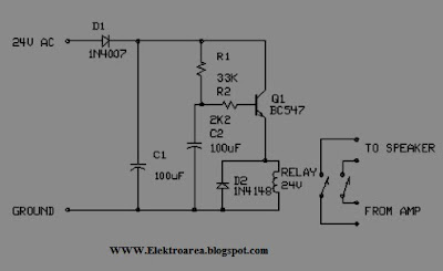
The following is a series of speakers delay relay useful as a delaying the speakers. The purpose of this delay circuit is as a deterrent to prevent pounding of the very first amplifier is turned on.

This delay circuit has the advantage that is: if there konsleting, relationship with the speaker amplifier circuit will be immediately cut off, so that the speaker is safe from fire. waiting time or delay time is about 5 seconds, and can be altered by changing the condenser C2 with elco smaller value. The time needed to re-open relay if the current cut off about 0.5 seconds.


Relay Penunda SpeakerSkema Rangkaian Relay Penunda Speaker


About Relay Contacts


A relay is an electrically operated switch. Electric current through the coil of the relay creates a magnetic field which attracts a lever and changes the switch contacts. The coil current can be on or off so relays have two switch positions


Gambar Relay PWR SPST 16A 24VDC


A simple electromagnetic relay, such as the one taken from a car in the first picture, is an adaptation of an electromagnet. It consists of a coil of wire surrounding a soft iron core, an iron yoke, which provides a low reluctance path for magnetic flux, a movable iron armature, and a set, or sets, of contacts; two in the relay pictured. The armature is hinged to the yoke and mechanically linked to a moving contact or contacts. It is held in place by a spring so that when the relay is de-energised there is an air gap in the magnetic circuit. In this condition, one of the two sets of contacts in the relay pictured is closed, and the other set is open. Other relays may have more or fewer sets of contacts depending on their function. The relay in the picture also has a wire connecting the armature to the yoke. This ensures continuity of the circuit between the moving contacts on the armature, and the circuit track on the Printed Circuit Board (PCB) via the yoke, which is soldered to the PCB.

READMORE...

Rangkaian Pengusir Serangga

In this section of talk about a type of insect repellent, insect repellant is a circuit that will repel insects from your home or yard with effectively. This circuit uses the frequency of bullying for the insect so the insect will go.
Pengusir SeranggaSkema Rangkaian Pengusir Serangga


For this skesta insect repellent should be installed inside or outside the home can / for speaker. This series of in-circuit oscilator adl PLL circuit / phase looked loop by using a CMOS 4047 with frequency 22 khz.gunakan external power supply for better results.

IC 4047 Description

The CD4047B is capable of operating in either the monostable or astable mode. It requires an external capacitor (between pins 1 and 3) and an external resistor (between pins 2 and 3) to determine the output pulse width in the monostable mode, and the output frequency in the astable mode.


Absolute Maximum Ratings IC IC 4047

DC Supply Voltage (VDD)...........-0.5V to +18VDC
Input Voltage (VIN)...............-0.5V to VDD +0.5VDC
Storage Temperature Range (TS)....-65°C to +150°C
Power Dissipation (PD)
Dual-In-Line...................... 700 mW
Small Outline..................... 500 mW
Lead Temperature (TL)
(Soldering, 10 seconds)........... 260°C.

READMORE...

Saturday, November 14, 2009

Menguji Dioda Menggunakan Multi Meter

Menguji Dioda Menggunakan Multi Meter

In the diode consists of cathode and anode, and this is given one mark. Then the steps using a multimeter diode test is as follows:
  1. Turn the switch on the Ohm, let R x 1K
  2. Investigators Attach the red to the cathode (+) and black Investigators at the anode (-) diode
  3. If the needle moves multimeter that is good, but if the needle does not move means diodes have been broken or damaged
  4. Then a black investigator then attached to the cathode (+) and red pencolok attached to the anode (-). When the needle multimeter silent, means the diode is in good condition but if the move means that the diode has been leaked (damaged)

About Diode

A diode is the basic electronic component. It’s property is that it can conduct only in one direction. A diode can be made by joining a p type semiconductor and an n type semiconductor. At the junction point there will be a voltage drop due to the migration of carriers. The voltage at this barrier is known as barrier potential. Ideally the barrier potential is zero. But in practical case there will be a drop of 0.7 Volts.


Daftar BernomorWhen the P side of diode is connected to the positive of power supply and N region is connected to the negative of supply, the diode is said to be in forward biased condition. At this condition, if the applied voltage is greater than the barrier potential of the diode, it starts conduction. After the diode is arrived in the conduction mode, the drop across it remains at 0.7 V. After the conduction starts, if the voltage is increased further, current trough it increases linearly with voltage.

When the supply voltage is reversed the diode is said to be in reverse biased condition. Here there is no conduction at lower voltage values .If we increase the voltage value further ,it is observed that at a voltage the current sharply increases due to the breakdown of the P-N junction. This damages the device.

READMORE...

Thursday, November 12, 2009

Antena Pemancar Radio FM

The antenna serves to radiate signals and radio wave radiation. Antenna generally divided into two by the beam, ie

Omnidirectional (all directions). This antenna radiates radio waves strong kesegala same direction.

bidirectional (both directions). This antenna radiates radio waves as strong to just two directions. The two parameters that need to be considered on an antenna is the polarization and penguatannya. Simply put, an antenna has a vertical polarization if the antenna is placed in a position perpendicular to the earth. Antenna with vertical polarization will produce radio waves with vertical polarization, too. In addition to vertical, there are also berpolarisasi horizontal antenna, the antenna plays when the field parallel to the earth.


Antena Pemancar Radio  FM
Gambar antena FM Omnidirectional


One important factor in the FM antenna system installation is the antenna height. In the VHF band, provided that communication can take place is a LOS (Line Of Sight). So ideally communications on VHF, the antenna receiver and transmitter both have seen each other. So in between there must be no objects that can absorb radio energy.

So that radio amateurs in the VHF band is often stated that a better antenna has a small gain but higher than the antenna mounted with a large gain but low installed.

READMORE...

Rangkaian Penala Antena

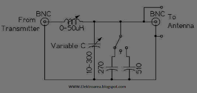
This is a series of antenna-tuning circuit or circuits for transmitting antenna placement SW 3-30 MHz wave / short wave 3-30 Mhz. If the placement is just right then the maximum energy from the transmitter will send out all the antenna through sehinnga nothing is wasted. To get a clear picture of the circuit is click on the picture below.


Rangkaian Penala AntenaSkema Rangkaian Penala Antena


This transmacth circuit function is to locate an appropriate impedance between the transmitting antenna that occurred in the ratio 1:1 SWR reading it, because in this placement is associated with a series of SWR / standing wave ratio. Thus the purpose of 1:1 is the one that came out was also one emitted by the antenna instead of just half saja.Impedansinya generally is 50 Ohm. With this circuit the maximum power that can pass this circuit is 50 Watt.


About SWR meter

The SWR meter or VSWR (voltage standing wave ratio) meter measures the standing wave ratio in a transmission line. This is an item of radio equipment used to check the quality of the match between the antenna and the transmission line.

SWR Meter Installation SWR Meter Installation

SWR Meter
SWR Meter Pic


The VSWR meter should be connected in the line as close as possible to the antenna. This is because all practical transmission lines have a certain amount of loss, causing the reflected power to be attenuated as it travels back along the cable, and producing an artificially low VSWR reading on the meter.

READMORE...

Sunday, November 08, 2009

Pengatur Kecepatan Motor Menggunakan PWM

So-called PWM or Pulse Modulation Witdh is a technique often used to control a load, for example, is the DC motor speed control, PWM techniques are often used.

Usually to make a simple PWM (for practice or introduction PWM) of the hobbyist to use some of the circuit made of Op-Amp, which consists of Schmitt Trigger circuit, integrator and comparator.

Diagram Pwm ControllerDiagram of PWM Controller


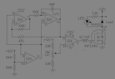
Schmitt Trigger function that produces a square wave will be converted by the integrator sawtooth wave or commonly also called Ramp, and Ramp compared with a reference voltage that can be changed much voltage. So the result is a PWM output.


Rangkaian PWM Motor/Light Controller
Skema Rangkaian Low Side PWM Motor/Light Controller


Rangkaian PWM Motor/Light Controller
Skema Rangkaian High Side PWM Motor/Light Controller


These two schematics are variations on another PWM circuit. The diagrams are for 12V operation only and there are high side (common ground) and low side (common +12V) versions. The low side version of the circuit uses an N Channel FET, the high side version of the circuit uses a P Channel FET. N Channel devices tend to handle more current than P Channel devices, they are also less expensive. The high side version of the circuit is useful when one side of the load has to be grounded.

This circuit can switch a fairly high amount of current, an IRFZ34N MOSFET can handle over 35 Amps if connected to a proper heat sink. Higher power FETs, such as the IRFZ48N or IRF1010Z can be substituted if even larger currents are required. It is also possible to connect multiple FETs in parallel for even more current capacity. Always use thermally conductive grease between the FET and the heat sink, and remember that the heat sink is electrically live.

Inductive loads (motors) may require special care since they can generate large voltage spikes that can damage the MOSFET. Replacing the 1N4002 with a fast recovery diode may help absorb the reverse voltage kick when driving an inductive load such as a motor. If you use these circuits for experiments with electric vehicles, be sure to install a circuit breaker in series with the battery, the circuit breaker should be easy to reach by the driver. This is especially important due to the fact that when MOSFETs fail, they often short out, leaving the motor on at full speed.

READMORE...

Multivibrator Astable Menggunakan IC 555

Multivibrator is an electronic circuit that at a certain time only one of two output voltage levels, except during the transition period. The transition (switching) between the two levels of output voltage occurs quickly. Two state level of the multivibrator output voltage, which is stable and Quasistable.

Astable multivibrator is called when the output voltage levels generated by the multivibrator circuit is quasistable. The circuit will only change the state of the output voltage level between the 2 conditions, each state has a fixed period. Multivibrator circuit will work independently and no longer need a trigger. Period of time each output voltage level is determined by the components making up the circuit.

multivibrator astable used IC 555Skema rangkaian multivibrator astable used IC 555


The picture above is the astable multivibrator circuit. This circuit will work when the voltage applied to Vcc ration and ground her. This circuit has two conditions are always changing with time. Because changing the type is known as astable multivibrator. With constant changes of 0 and 1, then the multivibrator is also called a bistable multivibrator (multivibrator which has two stable state of 0 and 1).


This change in cycle length can be calculated using the following equation:

Period = t1 + t2
t1 = 0.7 x (RA + RB) XC
t2 = 0.7 xRBxC.
.

READMORE...

Saturday, November 07, 2009

Rangkaian Multivibrator Monostable IC 555

Rangkaian Multivibrator Monostable IC 555 is a pulse generator circuit in which the duration of the pulse is determined by the R-C connected to IC 555 timer. In such a vibrator, one state of output is stable while the other is quasi-stable (unstable). For auto-triggering of output from quasi-stable state to stable state energy is stored by an externally connected capaci tor C to a reference level. The time taken in storage determines the pulse width. The transition of output from stable state to quasi-stable state is accom­plished by external triggering.


multivibrator monostable

Skema rangkaian multivibrator monostable IC 555


Capacitor C has to charge through resistance RA. The larger the time constant RAC, the longer it takes for the capacitor voltage to reach +2/3VCC. In other words, the RC time constant controls the width of the output pulse. The time during which the timer output remains high is given as

tp = 1.0986 RAC
where RA is in ohms and C is in farads. The above relation is derived as below. Voltage across the capacitor at any instant during charging period is given as


vc = VCC (1- e-t/RAC)
Substituting vc = 2/3 VCC in above equation we get the time taken by the capacitor to charge from 0 to +2/3VCC.

So +2/3VCC. = VCC. (1 – e-t/RAC) or t – RAC loge 3 = 1.0986 RAC
So pulse width, tP = 1.0986 RAC s 1.1 RAC
The pulse width of the circuit may range from micro-seconds to many seconds. This circuit is widely used in industry for many different timing applications.
.

READMORE...
 
Skema Rangkaian Elektronika